


Application
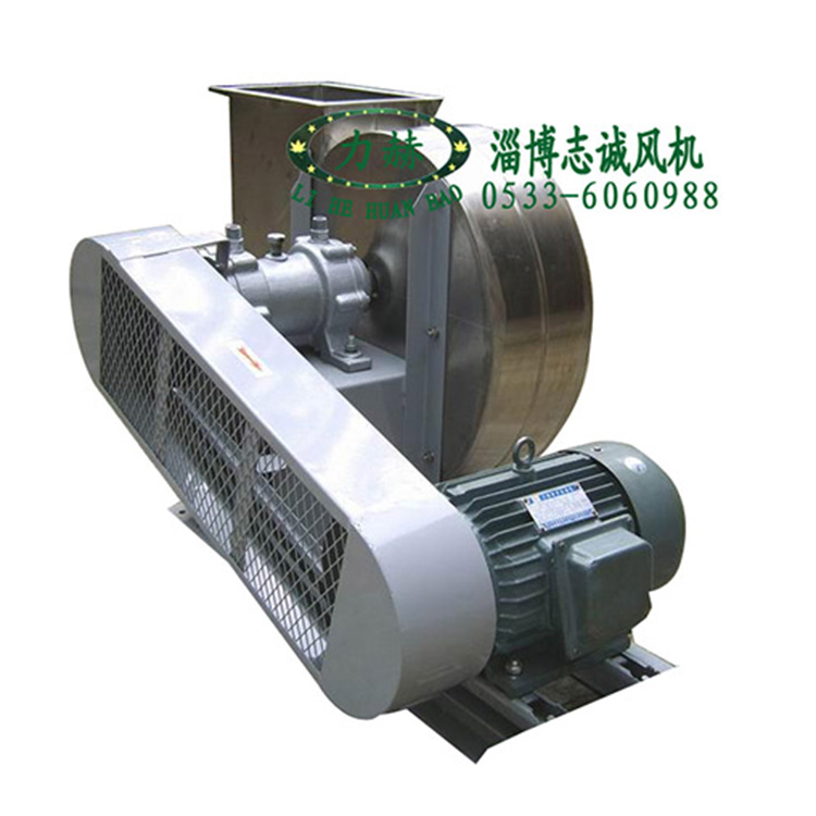
The W4-72-11 high-temperature fan is suitable for conveying non-corrosive gases with temperatures not exceeding 550°C. The dust and hard particles contained in the gas should not exceed 150mg/m³.
Form
1. This fan features single-sided intake and an articulated arm structure.
2. The fan is equipped with a Type C transmission.
3. Fans can be manufactured in two types: clockwise rotation and counterclockwise rotation. When viewed from the positive end of the motor, the impeller rotating in the clockwise direction is called a right-handed fan; rotating in the counterclockwise direction is called a left-handed fan.
Structural Features
1. The impeller is composed of 10 backward-tilted airfoil blades welded to an arc-conical wheel cover and a flat rear disk, made of heat-resistant stainless steel. It has been corrected for dynamic and static balance and tested for overspeed operation, ensuring safety and reliability.
2. The housing is a whole helical shell welded from steel plates.
3. The inlet duct is made as a whole, mounted on the side of the blower, with a cross-section parallel to the axis in a curved shape, allowing the gas to smoothly enter the impeller with minimal loss.
4. Transmission unit consists of the main shaft, belt wheels, and a water-cooled bearing housing.
Installation and Usage
Prior to installation, ensure all necessary materials and tools are prepared. Inspect all components of the fan, with particular attention to the impeller, housing, main shaft, and bearings. Any damage found should be repaired, and then clean the interior of the bearing housing with kerosene.
Three points must be noted during the installation process:
1. On some joint surfaces, apply a layer of lubricating oil or machine oil to prevent rust and reduce the difficulty of disassembly.
2. When bolting the upper joint surface, if there is a locating pin, it should be inserted first, followed by tightening the bolt.
3. Inspect the interior of the housing and other shell components; no tools or debris should be left inside or fall into them.
Installation Requirements:
1. When installing the fan, do not place the weight of the gas conveying pipe on the housing. Align the air inlet and impeller's axial and radial clearance dimensions according to the drawings, and maintain the axis in a horizontal position.
2. When installing the intake air duct, you can directly utilize the bolts of the intake air opening for connection. At this point, the intake air opening is secured by three countersunk screws.
3. After the fan installation, manually rotate the rotor to check for any tightness or scraping issues, ensure the wiring is correct, that all safety devices are in place, and that no one is near the rotating parts or entry/exit points. Only proceed with the trial operation after confirming safety.
4. After the motor is installed, fit the belt pulley or coupling guard. If no pipeline is connected at the intake port, a protective mesh or other safety device (user-provided) is also required. Other components are to be installed as per the diagram.
Due to the relationship between the fan's main shaft speed n and the internal power N:
Therefore, it is not advisable to alter the spindle speed without changing the motor capacity, as increasing the spindle speed can pose a risk of overloading and burning the motor. The motor power rating of the fan refers to the normal power consumption, plus mechanical losses and the required reserve, under specific operating conditions, not the power required when the outlet is fully open. If the fan operates without a pipeline connected to the inlet or outlet or without any external resistance, there is a risk of burning the motor. For safety reasons, valves should be added to the outlet or inlet pipeline of the fan, closing them during startup, then gradually and slowly opening them after operation until the specified operating conditions are reached, and pay attention to whether the motor current exceeds the limit.
Maintain
Regularly clean dust, dirt, and water, etc., from the fan and gas conveying pipelines, and prevent rust.
2. Power must be turned off and the machine stopped before repairing the fan. It is not allowed to be operated during repair. The switches should be supervised by a designated person to prevent accidental power-on during the process.
3. Regular inspections of the thermometer and oil marker sensitivity are required.
4. In addition to replacing lubricating oil after each disassembly and repair, regular oil changes are also required.
5. Thoroughly record, count, and verify the quantity of tools and raw materials before and after each maintenance to prevent any from being forgotten inside the fan or piping.
6. No personnel shall be standing within 10 meters of the inlet and outlet directions during the fan trial run.
7. Absolutely no unauthorized personnel are allowed to be present and围观 during installation, maintenance, or trial runs.
Faults and Causes
The main failures of fans include:
The bearing housing exhibits severe vibration.
1. The shaft of the fan is not concentric with the motor shaft, causing the coupling to be misaligned.
2. Shell or inlet with impeller friction.
3. Insufficient or inadequate base rigidity.
4. Loose bladed hub rivets or warped wheel disc.
5. Impeller shaft flange and shaft are loose, as well as coupling bolts.
6. Shell and bracket, bearing housing and bracket, bearing housing and seat connecting bolts are loose.
7. Poor installation of fan inlet and outlet ductwork, causing vibration.
8. Rotor unbalance.
9. Excessive fineness of pipes, with too fast wind speed.
Two: Excessive bearing temperature rise.
1. The bearing housing is experiencing severe vibration.
2. Poor quality grease, deterioration, excessive filling, and contamination with dust, sand, dirt, and other impurities.
3. Excessive or insufficient tension on bearing housing and saddle connecting bolts.
4. Axle and rolling bearing installation is misaligned, with the front and rear bearings not concentric.
5. Roller bearing damage.
3. Excessive motor current and high temperature rise.
1. The intake pipe gate or throttle valve was not fully closed while driving.
2. Exceeding the specified flow rate or air leakage in the ductwork.
3. The gas transported by the fan contains sticky substances or the temperature is too low, resulting in excessive gas density.
4. Low motor input voltage or single-phase power failure.
5. Misaligned coupling connection, too tight or uneven gap in the rubber ring.
6. Subject to severe vibration from the bearing housing.
7. Affected by the deterioration or failure of the parallel fan's operation.
Four: Belt Slipping Down
The two belt pulleys are not aligned with the corresponding slots.
Five, with pulsation
The two belt pulleys are too close together or the belt is too long.
Order Instructions
Please specify the model number, air volume, pressure, outlet angle, rotation direction, as well as the motor model, power, and speed when placing an order.
Performance and Options Table

