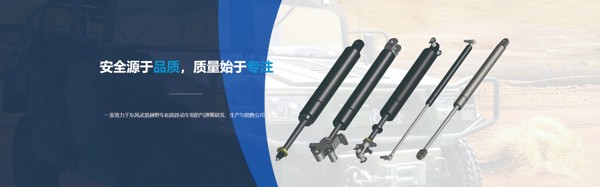

Air-powered support rods are used as pneumatic supports for lifting equipment, support structures, gravity balancing, and as substitutes for mechanical springs in equipment, etc.
Currently, pneumatic support rods are widely used in car engine hoods, rear door openings, plotters, aircraft mounts, printers, food processing machinery, modern automation equipment, fitness equipment, textiles, computers, furniture, woodworking machinery, and more. The pneumatic series gas springs are powered by high-pressure inert gases, maintaining a constant supporting force throughout the working stroke, featuring a shock absorption mechanism to avoid sudden impacts. This is a significant advantage over conventional springs, with the added benefits of easy installation and no need for maintenance.
The pneumatic support rod piston rod sleeve (including the piston rod sleeve, piston rod, and end components) accommodates steel, with a connector at the bottom of the piston rod sleeve and a through-hole in the upper wall. The piston rod has a piston at one end, which slides within the steel containment of the piston rod sleeve. The protrusion of the piston rod extends outward through the through-hole in the top wall of the piston rod sleeve. The end component is fixed to the acceptance steel between the piston and the top wall of the piston rod sleeve. The end component includes a guide sleeve, oil-free sliding bearing, block, and positioning bag. The oil-free sliding bearing is housed within the inner wall of the guide sleeve. The position steel, gears, and oil-free sliding bearing are all associated with the corresponding piston rod. As the corresponding piston rod moves back and forth within the piston rod sleeve, it contacts the four-plate layer of the oil-free sliding bearing, which acts to lubricate the piston rod, enhancing the wear resistance of the pneumatic support rod and preventing noise generation.
Installation Instructions for Pneumatic Support Rods: 1. The pneumatic support rod should be installed facing downwards; installing it in reverse can reduce friction, ensuring resistance quality and cushioning performance. 2. Determining the base installation location is crucial for confirming the proper operation of the pneumatic support rod.
Pneumatic support rods must be set up correctly, as shown in the figure below. That is, when closed, they move beyond the centerline of the structure. Otherwise, the pneumatic support rods often automatically open. 3. The pneumatic support rods must not be subjected to any tilting or lateral forces during operation and should not be used as handrails. 4. To ensure the reliability of the seal, the surface of the pneumatic support rod must not be damaged, and it is strictly prohibited to apply paint or chemicals on the pneumatic support rod. It is not allowed to first set the pneumatic support rod in the required position and then spray or paint it. 5. Pneumatic support rods are high-pressure products and must not be arbitrarily dissected, disabled, or collided with. Operating temperature range: -35 ~ 60°C. (Manufacturing 80°C, Development) 7. When installing the connection points, rotation must be smooth without any jamming. 8. The dimensions must be reasonable, with the force size moderate, and the piston rod stroke size should leave a 10mm margin.
