


Product Description
Brand Huoku Group Model CFW-60/0.8
Material: Stainless Steel, Diameter: 2916mm
Application Range -162℃ Volume 60000L
Heat Exchange Area - See drawing m², Ambient Temperature - See drawing °C
Wall Thickness: 8mm, External Dimensions: φ2916*14929mm
Origin: Shandong Heze

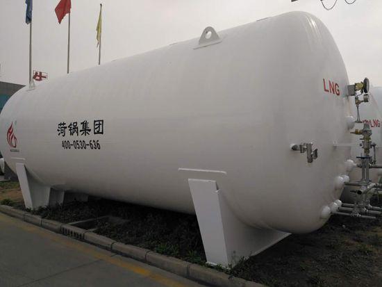
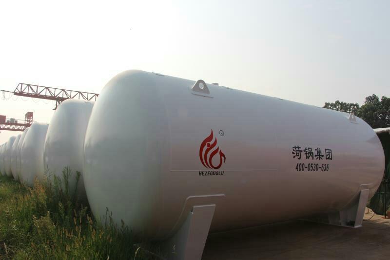
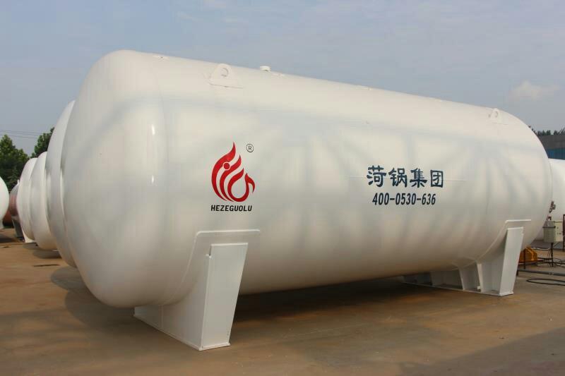
LNG Tank, Low-Temperature Natural Gas Tank, 60 Cubic Meter LNG Tank, Imported Paint from the USA, High Vacuum Level
1. Preparatory Work
Tanks should undergo a leak tightness test, blow-down treatment, and valve and instrument inspection before being put into service.
1.1 Airtightness Test
The tank should undergo a system airtightness test after installation is complete or the inner cylinder returns to normal temperature, prior to filling with low-temperature liquid. The test pressure should be the tank's maximum working pressure, using oil-free dry air or dry nitrogen as the test gas. The test duration is determined by the tank size but must not be less than 4 hours.
1.2 Blowing Treatment
After the airtightness test passes, the inner tank system must be purged with oil-free dry air or dry nitrogen to remove moisture. After purging with dry air or nitrogen, the product gas should also be used for purging. During purging, gases lighter than air are added from the top, through the vent valve, and the liquid进出口 valves are used to expel them from the bottom. To accelerate the removal of moisture inside the tank, the purge gas can be heated to 80-100°C. Each pipe and valve should be purged separately, especially the level gauge and pressure gauge, which should be purged at the joints to remove water from the pipes. Liquid filling can only begin once the dew point of the gas expelled from the inner tank system meets the required standard.
1.3 Valve Instrument Inspection
Before filling with low-temperature liquid, ensure that the valves are in the correct position, the instruments are responsive and reliable, and the liquid level gauge connections are unobstructed.
2. Filling: divided into initial filling and supplementary filling.
2.1 Initial Filling (referring to filling while the inner cylinder is in a heated state). The steps are as follows:
2.1.1 Connect the filling pipeline.
2.1.2 Remove air from the filling pipeline (this should be done before each filling), and before the upper liquid inlet and outlet valves are opened, place a small amount of liquid into the outlet pipeline from the liquid source valve. Simultaneously, open the residual liquid drain valve for the pipeline, and clean it to remove moisture and dust impurities from the pipeline.
2.1.3 Open the inner pipe vent valve and pressure gauge valve, and simultaneously start the level gauge.
2.1.4 Open the upper liquid inlet valve to allow liquid to enter from above. Since the inner cylinder is in a hot state, the opening of the upper liquid inlet valve should be small to allow the pipeline and inner cylinder to cool slowly to the temperature of the liquid being filled. Once the inner cylinder's vent valve stabilizes the exhaust, you can open the upper liquid inlet valve wider to increase the filling speed.
2.1.5 When the liquid level indicator shows a liquid level, open the liquid inlet and outlet valves, and close the upper liquid inlet valve to switch from upper to lower liquid inlet.
2.1.6 When the liquid fills the indicator valve (already opened) and sprays out, it indicates that the storage tank is full of liquid. Immediate closure of the liquid in and out valves is required, stop the filling process, and simultaneously open the pipeline residual liquid discharge valve to expel the remaining gas and liquid in the filling pipeline.
2.1.7 Disassemble the filling pipeline upon completion of filling.
2.2 Additional Refilling (refers to the inner cylinder already having low-temperature liquid, no longer requiring cooling of the inner cylinder)
2.2.1 Similar to the initial filling, the difference is that the filling quantity can be increased from the start, and close attention must be paid to pressure changes during the filling process. If liquid is directly introduced through the liquid in/out valves, when the pressure rises significantly, you can switch from bottom (lower) filling to top (upper) filling to reduce the pressure.
2.2.2 Additionally, from a pressure perspective, it can be categorized into atmospheric filling and pressure-filled filling.
2.2.3 During the atmospheric filling process, the inner cylinder's vent valve remains open, allowing the inner cylinder to be in communication with the atmosphere, hence the term "atmospheric filling."
During pressure filling, the vent valve is closed, and the pressure inside the tank is higher than atmospheric pressure, hence the term "pressure filling." However, the working pressure of the storage tank should be greater than 2 Kg/cm2. Whether under standard atmospheric pressure or engineering atmospheric pressure, 1 Kg/cm2 = 98,100 Pa = 0.0981 MPa.
3. Boost Pressure
When transferring the liquid in the tank to another storage tank or for vaporization, the internal cylinder pressure needs to be increased. The extent of the increase in pressure should be determined based on the actual usage requirements of the user, but it must not exceed the maximum working pressure of the tank.
Its boost program is:
3.1 Check if the pressure gauge and level gauge are in working condition.
3.2 Ensure the gas valve is fully open.
3.3 Slowly open the supercharger inlet valve (boost valve) to allow the liquid to vaporize in the supercharger. If the drainage speed is fast, the inner cylinder pressure will drop rapidly, and you can open the boost valve wider. When the pressure reaches the required working pressure, reduce or completely close the supercharger inlet valve; at this point, the liquid in the supercharger will continue to evaporate until the desired pressure is reached. During the boost process, closely monitor the pressure gauge readings.
4. Liquid Discharge
There are three forms of liquid discharge.
4.1 Carburetor Drain
Once the pressure inside the tank reaches the required level, the drain valve can be opened to supply liquid to the vaporizer, heating and vaporizing it for delivery to the usage site. This is the primary drainage method for tanks equipped with a vaporizer storage.
4.2 Liquid discharge through进出口 valves
This drainage process involves supplying liquid through a flexible hose to tanker trucks or larger storage tanks, with the operational procedure essentially similar to filling, except that the liquid inlet and outlet valves have been switched from intake to discharge.
4.3 Drainage valve (also known as liquid discharge valve) or direct draining through Dewar tube
This draining method involves supplying liquid to portable small containers like Dewar flasks by connecting the metal hose from the small container to the drain valve (or through a Dewar tube) and then opening the liquid outlet valve to supply the liquid. This draining quantity is relatively small, and for fixed storage tanks, it may not require pressure boost depending on the specific situation, allowing for external liquid supply.
5. Storage
Liquid storage includes two methods: atmospheric storage and pressure storage.
5.1 At atmospheric pressure storage
During atmospheric storage, the vent valve of the inner cylinder is always open, allowing the gases from natural evaporation to escape through this valve into the atmosphere, preventing the tank pressure from rising. Since the natural evaporation is minimal, the vent valve only needs to be slightly open. (The opening should be adjusted to maintain constant tank pressure.)
5.2 Pressure Vessel Storage
During the pressurized storage process, the vent valve is closed as the gaseous vapor from natural evaporation remains inside the tank, causing the inner cylinder pressure to gradually increase. At this point, the pressure gauge indicates pressure. When the inner cylinder pressure reaches working pressure, the vent valve should be immediately opened to relieve the pressure.
6. Simultaneous filling and draining issues
Many occasions require a continuous supply of gas, and this is achievable with two or more tanks. However, when there is only one storage tank, whether a continuous gas supply is possible hinges on whether simultaneous charging and discharging can be accomplished in the tank. If liquid is being transferred to a fixed storage tank using tank trucks, generally, for simultaneous charging and discharging to be feasible, the following conditions should be met:
6.1 The working pressure of fixed storage tanks should be above 0.02 Mpa.
6.2 During the liquid filling process, the upper liquid inlet valve and the liquid inlet and outlet valves should be adjusted frequently, as filling from the top (upper) can decrease the tank pressure, while filling from the bottom (lower) can increase the tank pressure.
6.3 When both filling and draining are in progress, if the liquid from the bottom (lower part) still does not meet the pressure requirements, you can open and adjust the size of the pressure booster valve to maintain stable pressure inside the tank.
7. Maintain
7.1 Do not tamper with the outer cylinder's explosion-proof device and vacuum valve, as doing so will destroy the vacuum of the storage tank.
7.2 The shell is a pressure vessel subject to atmospheric pressure. Collision is strictly prohibited to prevent damage to the shell and affect the vacuum degree.
The tank vacuum level is checked every six months. To measure, simply unscrew the protective cap on the metal thermocouple and insert the plug of the thermocouple vacuum gauge, then you can know the true vacuum level of the sandwich.
7.3 After several years of use, the vacuum level in the storage tank may drop below 66.66 Pa, at which point a re-evacuation is required.

LNG Storage Tank, Low-Temperature Natural Gas Storage Tank, 60 Cubic Meter LNG Storage Tank, Imported Paint from the USA, High Vacuum Degree
Product Description
Brand Hoogou Group Model CFW-30/0.8
Material: Stainless Steel, Diameter: 2916mm
Application Range -162℃ Volume 30000L
Heat Exchange Area - See drawing m², Ambient Temperature - See drawing °C
Wall Thickness: 8/10mm, External Dimensions: 2916*8289mm
Origin: Shandong, Heze

30立方立式lng储罐 卧式LNG储罐 低温天然气储罐厂家
The low-temperature storage tank is a double-layer structure, with the inner tank storing low-temperature liquids, withstanding the pressure and low temperatures of the medium. The material of the inner tank is a low-temperature-resistant alloy steel (0Crl8Ni9). The outer shell serves as a protective layer for the inner tank, maintaining a certain gap to form an insulating space, withstanding the gravitational loads of the inner tank and medium as well as the vacuum negative pressure of the insulating layer. The outer shell does not come into contact with the low temperature and is made of container steel. The insulating layer is mostly filled with mica sand, and a high vacuum is drawn. The evaporation rate of the low-temperature storage tank is generally less than 0.2%.
LNG tanks are categorized by capacity
(1) Small (5-50 m³): Commonly used for civil LNG refueling stations and civil gas liquefaction stations. (2) Medium (50-100 m³): Often utilized in industrial gas liquefaction stations. (3) Large (100-1000 m³): Suitable for small-scale LNG production facilities.
(4) Large (10,000-40,000 m3): For base load and peak-shaving liquefaction units. (5) Extra-large (40,000-200,000 m3): For LNG receiving terminals.
LNG tanks are categorized by shape
Spheres: Generally used for medium to small capacity storage tanks. (2) Cylinders: Used in storage tanks of various capacities. LNG Storage Tanks, Categorized by Placement (1) Above Ground: Located on the ground. (2) Underground: Located beneath the ground.
Determination of Design Pressure and Calculated Pressure
Currently, the majority of 100m3 vertical LNG storage tanks have a maximum working pressure of 0.8MPa. According to the GB150 "Steel Pressure Vessels" regulation, when the maximum working pressure of the storage tank is 0.8MPa, the design pressure can be taken as 0.84MPa. The filling factor of the tank is 0.95, and the net pressure of the liquid column in the inner tank after filling with LNG is 0.062MPa. The absolute pressure between the inner and outer tanks is 5Pa, so the calculated pressure of the inner tank is 1.01MPa.
The primary function of the outer container is to fix the inner container and the insulating material in a suspended or supported manner, while forming a high vacuum insulating layer with the inner container. The loads acting on the outer container are mainly the gravitational loads of the inner container and the medium, as well as the vacuum negative pressure of the insulating layer. Therefore, the outer container is an external pressure vessel, with a design pressure of -0.1 MPa.
Material selection for LNG tanks
During normal operation, the working temperature of the LNG storage tank is -162.3°C. Before the first use, the tank must be pre-cooled using liquid nitrogen at -196°C, so the design temperature of the tank is -196°C. The inner tank must withstand both the working pressure of the medium and the low temperature of LNG, requiring the material to have excellent comprehensive mechanical properties at low temperatures, particularly good low-temperature toughness. Therefore, the inner tank material is SS30408. Based on the calculated pressure of the inner tank and the selected material, the calculated thickness and design thickness are 11.1mm and 12.0mm, respectively. As a normal temperature external pressure vessel, the outer tank material is selected as low-alloy steel 16MnR, with a design thickness of 10.0mm.
LNG Tank接管Design
Tapping ports on the inner tank of the storage tank include: inlet liquid port, outlet liquid port, liquid outlet port, vapor phase port, level measurement port, upper level gauge port, lower level gauge port, and 8 process manholes. The material of the tapping ports on the inner tank is all OCrl8Ni9.
For easy regular measurement of vacuum and evacuation, a vacuum evacuation port is provided in the lower cover of the outer casing (the port is sealed after evacuation). To prevent vacuum failure and the leakage of the inner casing medium into the outer casing, a burst-proof device is set up on the outer casing cover.
30立方立式lng储罐 卧式LNG储罐 低温天然气储罐厂家


Wholesale Pricing for Liquefied Natural Gas Storage Tanks - Top Quality Liquefied Natural Gas Storage Tank Wholesale Prices - Gas Conduction Oil Boiler Liquefied Natural Gas Storage Tanks by Shandong He Guo Group - Professional Liquefied Natural Gas Storage Tank Supplier
