


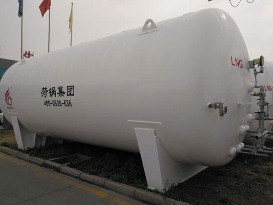
Product Description
Brand Hegu Group Model CFW-60/0.8
Material: Stainless Steel, Diameter: 2916mm
Application Range: -162℃; Volume: 60,000L
Heat Exchange Area - See drawing m², Ambient Temperature - See drawing °C
Wall Thickness: 8mm, Outer Dimensions: φ2916*14929mm
Origin: Shandong Heze

LNG Tank, Low Temperature Natural Gas Tank, 60 Cubic Meter LNG Tank, Imported Paint from the USA, High Vacuum Level
1. Preparatory Work
Tanks should undergo a leak test, purge treatment, and valve instrument inspection before being put into use.
1.1 Airtightness Test
The tank should undergo a system airtightness test after installation is complete or the inner cylinder returns to normal temperature, before filling with low-temperature liquid. The test pressure should be the tank's maximum working pressure, and the test gas should be oil-free dry air or dry nitrogen. The test duration is determined by the tank size but must be no less than 4 hours.
1.2 Blowing Treatment
After the airtightness test passes, the inner tank system must be purged with oil-free dry air or dry nitrogen to remove damp air. After purging with dry air or dry nitrogen, the product gas should also be used for purging. During purging, gases lighter than air are added from the top of the tank through the vent valve, and the bottom is vented through the liquid inlet and outlet valves. To accelerate the removal of moisture inside the tank, the purge gas can be heated to 80-100°C. Each pipe and valve should be purged individually, especially the level gauge and pressure gauge, which should be purged at the joints to remove moisture from the pipes. This should continue until the dew point of the gas from the inner tank system meets the requirements before filling can begin.
1.3 Valve Instrument Inspection
Before filling with low-temperature liquid, ensure the valves are in the correct position, the instruments are responsive and reliable, and the liquid level gauge connections are unobstructed.
2. Filling: divided into initial filling and top-up filling.
2.1 Initial Filling (referring to filling while the inner cylinder is in a heated state). The steps are as follows:
2.1.1 Connect the filling pipeline.
2.1.2 Perform blow-out on the filling pipeline (this should be done before each filling), and before the upper liquid inlet and outlet valves are opened, place a small amount of liquid into the output pipeline from the liquid source valve. Simultaneously, open the pipeline residual liquid drain valve, and clean the pipeline to remove moisture and dust impurities within it.
2.1.3 Open the vent valve and pressure gauge valve of the inner tube, and simultaneously start the level gauge.
2.1.4 Open the upper liquid inlet valve to fill from the top. Due to the inner cylinder being in a hot state, the opening of the upper liquid inlet valve should be minimal to allow the piping and inner cylinder to gradually cool to the temperature of the low-temperature liquid being filled. Once the inner cylinder's vent valve stabilizes and exhausts, you can open the upper liquid inlet valve wider and increase the filling speed.
2.1.5 When the liquid level gauge indicates a liquid level, open the liquid inlet and outlet valves, and close the upper liquid inlet valve to switch from upper to lower liquid inlet.
2.1.6 When the liquid fills the indicator valve (which has already been opened) and sprays out, it indicates that the storage tank is full of liquid. Immediate closure of the liquid inlet and outlet valves is required, halt the filling process, and simultaneously open the pipeline residual liquid discharge valve to expel the remaining gas and liquid in the filling pipeline.
2.1.7 Disassemble the liquid filling pipeline after filling is complete.
2.2. Fill-up (referring to the inner cylinder already containing low-temperature liquid, no longer requiring cooling of the inner cylinder)
2.2.1 Similar to the initial filling, the difference is that the filling quantity can be increased from the start, and the pressure changes during the filling process must be closely monitored. If filling directly from the liquid inlets and outlets, when the pressure rises significantly, switch from filling from the bottom to the top to reduce the pressure.
2.2.2 Additionally, from the perspective of pressure, it can be categorized into atmospheric filling and pressure-filled filling.
2.2.3 During the atmospheric filling process, the inner cylinder's exhaust valve is always open, allowing the inner cylinder to be in communication with the atmosphere, hence the name "atmospheric filling."
Under pressure filling in progress, the vent valve is closed, and the tank pressure is higher than atmospheric pressure, hence the term "under pressure filling." However, the working pressure of the storage tank should be greater than 2 Kg/cm2. Whether under standard atmospheric pressure or engineering atmospheric pressure, 1 Kg/cm2 = 98,100 Pa = 0.0981 MPa.
3. Boosted Pressure
When transferring the liquid in the tank to another storage tank or for vaporization, it is necessary to increase the internal cylinder pressure. The increase in pressure should be determined based on the actual usage requirements of the user, but it must not exceed the maximum working pressure of the tank.
Its boost program is:
3.1 Check if the pressure gauge and level gauge are in working condition.
3.2 Ensure the gas valve is fully open.
3.3 Slowly open the pre-compressor valve (boost valve) to allow liquid into the compressor to vaporize. If the drainage speed is fast, the internal cylinder pressure will drop rapidly, in which case, open the boost valve wider. Once the pressure reaches the desired operating pressure, partially or completely close the pre-compressor valve. At this point, the liquid inside the compressor will continue to evaporate until the desired pressure is achieved. During the boosting process, closely monitor the pressure gauge for any changes in readings.
4. Liquid Discharge
Three forms of liquid discharge
4.1 Carburetor Drain
Once the pressure inside the tank reaches the required level, the drain valve can be opened to supply liquid to the vaporizer, causing it to heat up and vaporize for delivery to the site of use. This is the primary drainage method for tanks equipped with a vaporizer.
4.2 Liquid discharge through liquid进出口 valves
This draining process involves supplying liquid through a输液管 into tanker trucks or larger storage tanks, with the operating procedure essentially the same as filling, except the liquid inlet and outlet valves are switched from intake to discharge.
4.3 Drainage valve (also known as liquid discharge valve) or draining directly through a Dewar tube
This type of draining is for supplying liquid to portable small containers like Dewar flasks. Simply connect the metal flexible tube from the small container to the drain valve (or through a Dewar tube) and open the liquid outlet valve to supply the liquid. This draining capacity is small, and for fixed storage tanks, it may not require pressurization based on specific conditions, allowing for external liquid supply.
5. Storage
Liquid storage includes two methods: atmospheric storage and pressurized storage.
5.1 Atmospheric Storage
During atmospheric storage, the vent valve of the inner cylinder is always open, allowing gases from natural evaporation to escape through this valve into the atmosphere, preventing the pressure inside the tank from rising. Since the natural evaporation is minimal, the vent valve only needs to be slightly open. (The opening should be adjusted to maintain constant pressure inside the tank.)
5.2 Pressure-Vessel Storage
During pressurized storage, the vent valve is closed. As the gaseous product from natural evaporation remains inside the tank, the internal pressure gradually increases. At this point, the pressure gauge indicates pressure. When the internal pressure reaches the working pressure, the vent valve should be immediately opened to relieve pressure.
6. Issues with simultaneous filling and draining of fluids
There are many occasions that require a continuous supply of gas, which is met by having two or more tanks. However, for a single storage tank, whether it can supply gas continuously hinges on whether it can perform filling and emptying simultaneously. Generally, when using tank trucks to fill liquid into fixed storage tanks, simultaneous filling and emptying should meet the following conditions:
6.1 The working pressure of fixed storage tanks should be above 0.02 Mpa.
6.2 During the liquid filling process, the upper liquid inlet valve and the liquid inlet and outlet valves should be frequently adjusted, as liquid entering from the top (top) can reduce the pressure inside the tank, while liquid entering from the bottom (bottom) can increase the pressure inside the tank.
6.3 During simultaneous filling and emptying, if the liquid is being introduced from the bottom and the pressure requirements cannot be met, adjust the size of the pressure booster valve to maintain stable internal pressure within the tank.
7. Maintain
7.1 Do not tamper with the explosion-proof device of the outer cylinder or the vacuum valve; otherwise, it will destroy the vacuum degree of the storage tank.
7.2 The housing is an external pressure vessel that withstands atmospheric pressure; collision is strictly prohibited to prevent damage to the housing and affect the vacuum degree.
The tank vacuum level is checked every six months. To measure, simply unscrew the protective cap on the metal thermocouple and insert the plug of the thermocouple vacuum gauge, then you can determine the actual vacuum level of the sandwich.
7.3 After several years of use, the vacuum level in the storage tank may drop below 66.66 Pa, in which case a re-evacuation is required.

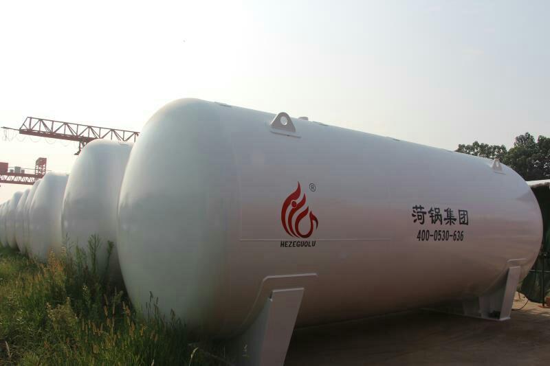
LNG Tank, Low Temperature Natural Gas Tank, 60 Cubic Meter LNG Tank, Imported Paint from the USA, High Vacuum Degree
Product Description
Brand: He Guo Group Model: CFW-30/0.8
Material: Stainless Steel, Diameter: 2916mm
Application Range -162℃ Volume 30000L
Heat Exchange Area - See drawing m², Ambient Temperature - See drawing °C
Wall Thickness: 8/10mm, External Dimensions: 2916*8289mm
Origin: Shandong Heze
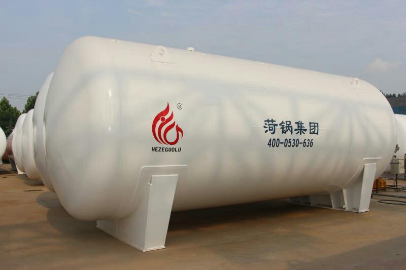
Horizontal LNG Tank 30 Cubic LNG Tank 60 Cubic LNG Tank 100 Cubic Natural Gas Tank

The low-temperature LNG storage tank is a double-layer structure, with the inner shell storing low-temperature natural gas liquids, withstanding the pressure and low temperature of the medium. The material of the inner shell is SS30408. The outer shell serves as the protective layer for the inner shell, maintaining a certain gap to form an insulating space, and bearing the gravity loads of the inner shell and the medium as well as the vacuum negative pressure of the insulating layer. The outer shell does not come into contact with the low temperature and is made of container steel. The insulating layer is mostly filled with pumice sand, and high vacuum is drawn. The evaporation rate of the low-temperature LNG storage tank is generally less than 0.2%.

Low-Temperature LNG Storage Tank Structural Design
1.1 Liquid Filling System
The filling process is divided into upper filling and lower filling, with a quick connector CN-1 and a four-way connector connecting to the upper filling valve V3 and the lower filling valve V2, respectively, and tubes and transition joints leading to the inner cylinder.
Tubes are selected in sizes φ28×2 and φ45×3.5.
1.2 Drainage System
The valve V6 can directly drain fluid, connected from the lower part of the cylinder; the pipe is selected in φ45×3.5. V6 is chosen with 32gDA25C, with a specification of DN40PN4.0.
1.3 Vacuum Degree Measurement System
VR vacuum silicon tube, used to measure the vacuum degree of the tank's insulation layer, connected to the evacuation pipe of the insulation layer. When the vacuum degree of the vacuum layer exceeds 3Pa, the insulation layer should be re-evacuated to maintain the vacuum degree of the insulation layer and enhance the insulation effect.
1.4 Vacuum Insulation System
VV vacuum vent, using CF-40 with DN 40, for vacuum extraction. Close VV when the vacuum level reaches the required standard to maintain the interlayer vacuum.
1.5 Level Measurement System
Two pipelines are extracted from the top and bottom of the cylinder respectively, with the top being the vapor phase and the bottom the liquid phase, connected together by the level gauge valve. L1 level gauge valve PS×Z-1, the gas line connects to the pressure gauge valve and the pressure gauge, with the liquid level measuring range of 0 to 6 meters of water column.
1.6 Full Mouth Measurement
Install the pipeline based on the set liquid level. When the liquid level reaches the set value, it flows downward into the fill valve MV. As the liquid fills, this valve opens until liquid starts to flow out, indicating the tank is full. Close the valve and select a 32gDA10C valve. Specification: DN20 PN4.0.
1.7 Self-Pressurizing System
The pressure booster valve V1 is connected to the PBC-1 supercharger, which uses the CFB03-00 model. It vaporizes a portion of the liquid flowing from the tank and introduces it into the inner tank, thereby increasing the pressure inside the tank, causing the liquid to be expelled under pressure.
1.8 Gas Venting System
When the pressure at the top of the container increases, gas is released through the pipeline and passes through the vent valve E1, then to a check valve CV. Since gas can only flow out, a check valve is used to prevent backflow. Therefore, a flame arrester is connected after the check valve because gas release and contact with air may cause sparks. The flame arrester is there to prevent sparks from entering the inner tank with the gas, which could ignite and cause an explosion.

Horizontal LNG Storage Tank 30 Cubic LNG Storage Tank 60 Cubic LNG Storage Tank 100 Cubic Natural Gas Storage Tank


Shandong He Guo Group - Manufacturer of Liquefied Natural Gas Tanks - Direct Sales of Professional Liquefied Natural Gas Tanks - Heze Boiler Liquefied Natural Gas Tanks - In Stock Liquefied Natural Gas Tank Production
