


LNG Natural Gas Storage Tank, Cryogenic Low-Temperature Vessel
Low-temperature liquefied natural gas storage tank equipment is widely used in various industries of the national economy, including industry, agriculture, national defense, and scientific research. The application of natural gas storage equipment is increasingly widespread, primarily due to its advantages over traditional steel cylinders, such as convenient transportation, energy conservation, safety, reliability, purity assurance, and versatility. China's low-temperature storage tanks are developing towards high quality, diverse varieties, and large capacities.
Low-temperature liquid storage tanks are high-vacuum insulated stainless steel pressure vessels, designed for storing, transporting, and using liquefied natural gas, liquid oxygen, liquid nitrogen, liquid argon, or carbon dioxide. These low-temperature containers are manufactured according to GB18442 standards, and are used for reliable and cost-effective transportation and storage of low-temperature liquids, as well as on-site storage and supply of low-temperature liquid gases across a wide range of applications.

Manufactured fixed pressure vessels comply with the following regulations and standards:
1. TSG 21-2016 "Technical Supervision Regulation for the Safety Supervision of Fixed Pressure Vessels"
2. ASME Section I, Parts 1-4 - 2011 "Boilers and Pressure Vessels"
3. NB/T47014-2011 "Welding Procedure Qualification for Pressure Equipment"
4. NB/T47015-2011 "Code for Welding Procedure of Pressure Vessels"
5. GB/T25198-2010 "Pressure Vessel End Cap"
6. NB/T 47013-2015 Non-destructive Testing of Pressure Equipment
7. NB/T 47016-2011 "Mechanical Property Test of Welding Samples for Pressure Equipment Products"
8. JB/T4711-2003 "Coating and Packaging for Pressure Vessels"
9. GB/T18442-2011 "Fixed Vacuum Insulation Low-Temperature Pressure Vessel"

A low-temperature storage tank is a pressure vessel used for storing various low-temperature liquids, such as natural gas tanks, LNG tanks, liquid oxygen tanks, liquid argon storage tanks, and low-temperature liquid nitrogen tanks. Therefore, its safe operation rules should consider factors such as the gas risk characteristics, low-temperature maintenance effects, surrounding environmental conditions, and characteristics of the pressure vessel. So, what are the detailed operation rules for low-temperature storage tanks? Let's explore them together below.
1. Types of facilities and fire separations
Low-temperature storage tanks are classified as Class B, with the minimum fire resistance grade of two. The fire separation between low-temperature storage tanks should be no less than half the diameter of the larger tank among the two adjacent tanks. There are no fire separation requirements for oxygen storage tanks with a volume of 50m3 or less and their application buildings. The separation between nitrogen and argon storage tanks should meet construction and maintenance requirements and should not be less than 2m.
2. Lightning and Static Electricity Protection
The low-temperature storage tank area must have lightning and static electricity grounding devices, and it is required to invite a qualified unit for regular grounding resistance checks annually. The equipment, pipelines, and flange and threaded joints on the low-temperature storage tank should be connected with metal wires, with the cross-connected resistance being less than 0.03Ω.
Establish stringent procedures for the distribution, collection, and on-site handling of low-temperature steel materials, which is a crucial quality assurance method for the manufacturing of low-temperature pressure vessels. Particularly in the production site, as low-temperature steel can easily be mixed with general steel, failure to strictly manage it can leave significant safety risks. Low-temperature steel and welding rods should be handled by designated personnel in dedicated storage. After technical briefings, workers and handlers should be familiar with the identification of low-temperature steel and welding rods to prevent mixing with other steels. Records should be kept for material in and out of the warehouse, and remaining materials should be promptly relabeled. The surface quality of low-temperature steel requires high standards, and during storage and transportation, the surface should be protected and color-coded labels used for identification. Cutting and material preparation should be under the supervision of material handlers and promptly relabeled. Surface markings are not allowed on low-temperature steel, and identification should not be made by stamping. Steel plates and semi-finished products should be sorted by batch number and standard and stored on shelves. Preformed materials should be stored using fixtures and brackets, and it is strictly prohibited to place low-temperature steel materials, especially welding materials, directly on the ground. The distance from the bracket to the ground and walls should not be less than 300mm. The welding rod storage area should comply with relevant welding material handling regulations, with the temperature not below 10°C, and relative humidity not exceeding 60%, with proper records maintained. Welding rods should be dried for 2 hours at the specified temperature before use and then stored in a constant-temperature drying cabinet (100-150°C).
In the pressure vessels currently used in petrochemical enterprises, low-temperature pressure vessels account for a significant proportion. Due to their lower operating temperatures, the brittleness of the container materials increases correspondingly. Under the effect of tensile stress, the stressed components may suddenly experience brittle fractures at stress levels below the material's yield strength or below the allowable stress. Such fractures typically occur with minimal or no plastic deformation before or after the event, without overall yielding, and are often undetectable during routine production, posing a greater safety threat to petrochemical production. Therefore, for low-temperature pressure vessels, there is a need for an enhanced level of requirements in all stages from design, material selection, manufacturing to inspection, compared to non-low-temperature pressure vessels.

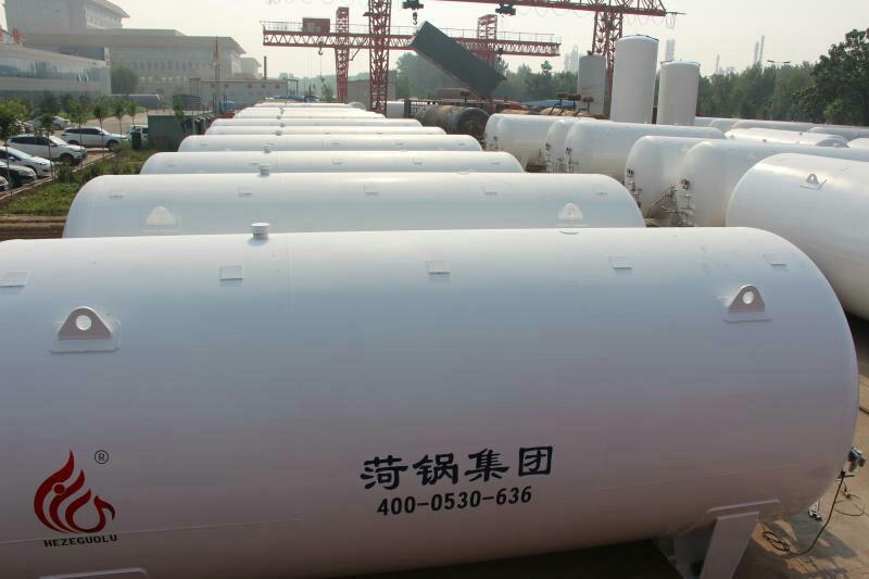
LNG natural gas storage tank, liquefied low-temperature container
Product Description
Brand Huoguo Group Model CFW-60/0.8
Material: Stainless Steel, Diameter: 2916mm
Application Range: -162℃; Capacity: 60,000L
Heat Exchange Area - See drawing m², Ambient Temperature - See drawing °C
Wall Thickness: 8mm, Outer Dimensions: φ2916*14929mm
Origin: Shandong Heze
LNG Storage Tank, Low Temperature Natural Gas Storage Tank, 60 Cubic Meter LNG Storage Tank, Imported Paint from the USA, High Vacuum Degree
1. Preparatory work
Tanks should undergo a leak test, blow-down treatment, and valve and instrument inspection before being put into use.
1.1 Airtightness Test
The tank should undergo a system airtightness test after installation is complete or the inner cylinder returns to normal temperature, prior to filling with low-temperature liquids. The test pressure shall be the maximum working pressure of the tank, using oil-free dry air or dry nitrogen as the test gas. The test duration shall be determined based on the tank size, but it must not be less than 4 hours.
1.2 Blowing Treatment
After the airtightness test is passed, the inner tank system must be purged with oil-free dry air or dry nitrogen to remove damp air. After the system is purged with dry air or nitrogen, it should also be purged with product gas. During the purge, gases lighter than air are added from the top through the vent valve, and the bottom is drained through the liquid inlet and outlet valves. To accelerate the removal of moisture inside the tank, the purge gas can be heated to 80-100°C. Each pipe and valve should be purged individually, especially the level gauge and pressure gauge, which should be purged at the joints to remove moisture from the pipes. The liquid filling can only begin once the dew point of the gas expelled from the inner tank system meets the required specifications.
1.3 Inspection of Valve Instruments
Before filling with low-temperature liquid, ensure that the valves are in the correct position, the instruments are responsive and reliable, and the liquid level gauge connections are unobstructed.
2. Filling: divided into initial filling and top-up filling.
2.1 Initial Filling (referring to the filling of the inner cylinder when it is in a heated state). The steps are as follows:
2.1.1 Connect the filling pipeline.
2.1.2 Perform blow-off on the filling pipeline (this should be done before each filling), and before the upper liquid inlet and outlet valves are opened, insert a small amount of liquid into the output pipeline from the liquid source valve. Simultaneously, open the pipeline residual liquid drain valve to clean the pipeline, removing moisture and dust impurities within.
2.1.3 Open the inner pipe drain valve and pressure gauge valve, and simultaneously activate the level gauge.
2.1.4 Open the upper liquid inlet valve to allow liquid to enter from above. Since the inner cylinder is in a hot state, the opening of the upper liquid inlet valve should be small to allow the pipeline and inner cylinder to cool slowly to the temperature of the liquid being filled. Once the inner cylinder's vent valve stabilizes the exhaust, you can open the upper liquid inlet valve wider to increase the filling speed.
2.1.5 When the liquid level indicator indicates a liquid level, open the liquid inlet and outlet valves, and close the upper liquid inlet valve to switch from upper to lower liquid inlet.
2.1.6 When the liquid fills the indicator valve (already opened) and sprays out, it indicates that the storage tank is full of liquid. Immediately close the liquid in and out valves, stop filling while opening the pipeline residual liquid discharge valve, and drain the residual gas and liquid in the filling pipeline.
2.1.7 Remove the filling pipeline after the filling process is complete.
2.2. Supplemental Fill (referring to the inner cylinder already having low-temperature liquid, no longer requiring cooling of the inner cylinder)
2.2.1 Similar to the initial filling, the difference is that the filling quantity can be increased from the start, and close attention must be paid to pressure changes during the filling process. If liquid is directly introduced through the liquid inlets and outlets, when the pressure rises significantly, to reduce the pressure, switch from bottom (lower) filling to top (upper) filling.
2.2.2 Additionally, from a pressure perspective, it can be divided into atmospheric filling and pressure filling.
2.2.3 During the normal pressure filling process, the inner cylinder's vent valve remains open, allowing the inner cylinder to be in communication with the atmosphere, hence the name normal pressure filling.
Under pressure filling in progress, the vent valve is closed, and the pressure inside the tank is higher than atmospheric pressure, hence the term "under pressure filling." However, the working pressure of the storage tank should be greater than 2 Kg/cm2. Whether under standard atmospheric pressure or engineering atmospheric pressure, 1 Kg/cm2 = 98100 Pa = 0.0981 MPa.
3. Boost Pressure
When transferring the liquid in the tank to other storage tanks or for vaporization use, the internal cylinder pressure needs to be increased. The extent of the pressure increase should be determined based on the user's actual requirements, but it must not exceed the tank's maximum working pressure.
The boost program is:
3.1 Check if the pressure gauge and level gauge are in working condition.
3.2 Ensure the gas valve is fully open.
3.3 Open the booster's inlet valve (boost valve) slowly to allow the liquid to vaporize within the booster. If the draining speed is rapid, the inner cylinder pressure will drop quickly; in this case, open the boost valve wider. When the pressure reaches the required working pressure, reduce or close the booster's inlet valve completely. At this point, the liquid inside the booster will continue to evaporate until it reaches the desired pressure. During the boosting process, closely monitor the pressure gauge readings.
4. Liquid Discharge
Three forms of liquid discharge
4.1 Fuel Injector Drain
Once the pressure inside the tank reaches the required level, the drain valve can be opened to supply liquid to the vaporizer, causing it to heat up and vaporize for use at the site. This is the primary drainage method for tanks equipped with a vaporizer storage tank.
4.2 Liquid discharge through liquid进出口 valves
This draining process utilizes a输液管 to supply liquid to tanker trucks or larger storage tanks. The operating procedure is essentially the same as for refueling, with the only difference being that the liquid inlets and outlets are switched from intake to drainage.
4.3 Discharge through a drain valve (also known as a liquid discharge valve) or directly via a Dewar tube
This type of drainage supplies liquid to portable small containers like Dewar flasks by connecting the metal flexible tube of the small container to the drainage valve (or through a Dewar tube), then opening the liquid outlet valve to supply the liquid. This drainage amount is small, and for fixed storage tanks, it may not require pressurization based on specific circumstances, allowing for the supply of liquid externally.
5. Storage
Liquid storage includes two methods: atmospheric storage and pressurized storage.
5.1 Atmospheric Storage
During atmospheric storage, the vent valve on the inner cylinder is kept open to allow the gas from natural evaporation to be released into the atmosphere, preventing the tank pressure from rising. Since the natural evaporation is minimal, the vent valve only needs to be slightly open. (The opening should be adjusted to maintain constant tank pressure.)
5.2 Pressure-Containing Storage
During the pressurized storage process, the vent valve is closed. As the gas from natural evaporation remains inside the tank, the internal pressure gradually increases. At this point, the pressure gauge indicates the pressure. When the internal pressure reaches the working pressure, the vent valve should be immediately opened to relieve pressure.
6. Simultaneous filling and draining issues
Many occasions require a continuous supply of gas, which is met when there are two or more tanks. However, for a single storage tank, whether the gas supply can be continuous hinges on whether simultaneous charging and discharging can be achieved. If liquid is being transferred to a fixed storage tank using tank trucks, generally, simultaneous charging and discharging should meet the following conditions:
6.1 The working pressure of fixed storage tanks should be above 0.02 Mpa.
6.2 During the liquid filling process, the upper inlet valve and the liquid inlet and outlet valves should be adjusted frequently, as liquid entering from the top (top) can reduce the tank's pressure, while liquid entering from the bottom (bottom) can increase the tank's pressure.
6.3 When both charging and discharging fluids simultaneously, if the fluid is being introduced from the bottom (lower part) and still cannot meet the pressure requirements, you may open and adjust the size of the boost valve to maintain stable pressure within the tank.
7. Maintain
7.1 Do not tamper with the outer cylinder explosion-proof device and vacuum valve; otherwise, it will破坏 the vacuum degree of the storage tank.
7.2 The housing is an external pressure vessel that withstands atmospheric pressure. Collision is strictly prohibited to prevent damage to the housing and affect the vacuum degree.
Tanks should be vacuum checked every six months. To measure, simply unscrew the protective cap on the metal thermocouple and insert the plug of the thermocouple vacuum gauge. This will reveal the true vacuum level between the walls.
7.3 After several years of use, the vacuum level in the storage tank may drop below 66.66 Pa, at which point a re-vacuuming is required.

LNG Tank, Low-Temperature Natural Gas Tank, 60 Cubic Meter LNG Tank, Imported Paint from the USA, High Vacuum Level


专业制造液化天然气储罐哪家好-知名液化天然气储罐制作-专业液化天然气储罐厂家直销-供应液化天然气储罐厂家
