


30, 60, 100 cubic meter LNG storage tanks, LNG gasification stations, and vehicle refueling station process and equipment selection
1. LNG, CNG, LPG - Meanings
CNG: Compressed Natural Gas is high-pressure natural gas compressed to 20MPa. Natural gas stored in high-pressure cylinders is used as fuel in CNG vehicles. High-pressure cylinder storage at normal temperature: 20MPa.
LNG: Liquefied Natural Gas (LNG) is natural gas cooled to -162℃ to form a liquid. It is stored in low-temperature tanks and used as fuel in LNG vehicles. Cylinder Low-Pressure Low-Temperature Storage: 1.6 MPa.
LNG and CNG refueling, storage, and supply systems have some differences, but natural gas ultimately enters the car engine in a gaseous state after being pressurized through a pressure regulator to 0.15 MPa for combustion and work.
LPG: Liquefied Petroleum Gas
2. Applications of LNG Storage Tanks: Gasification Stations and Auto Gas Filling Stations
LNG liquefaction plant
(1) Peak load and load balancing for urban pipeline gas supply and emergency adjustments
(2) Gas supply source for city municipal gas networks in areas where natural gas pipelines have not been laid.
(3) Gas sources for community supply: Boiler gas and domestic gas supply
(4) Gas source for corporate supply; (Image)
2. Gasoline Filling Station: Used for automotive fuel
III. Types of CNG Stations:
LNG vehicle refueling station
1) Conventional Station: Located at a fixed site, LNG is unloaded using unloading equipment, filled into storage tanks, and refueled into vehicles using fueling machines. (Image)
2) Skid-mounted Station: Equipment and facilities for gas stations are mounted on trucks or skids, offering high integration for easy transportation and relocation. Suitable for smaller-scale gas stations. (Image)
CNG Vehicle Refueling Station
3. L-CNG Vehicle Refueling Station
LNG Gasification Plant Major Equipment
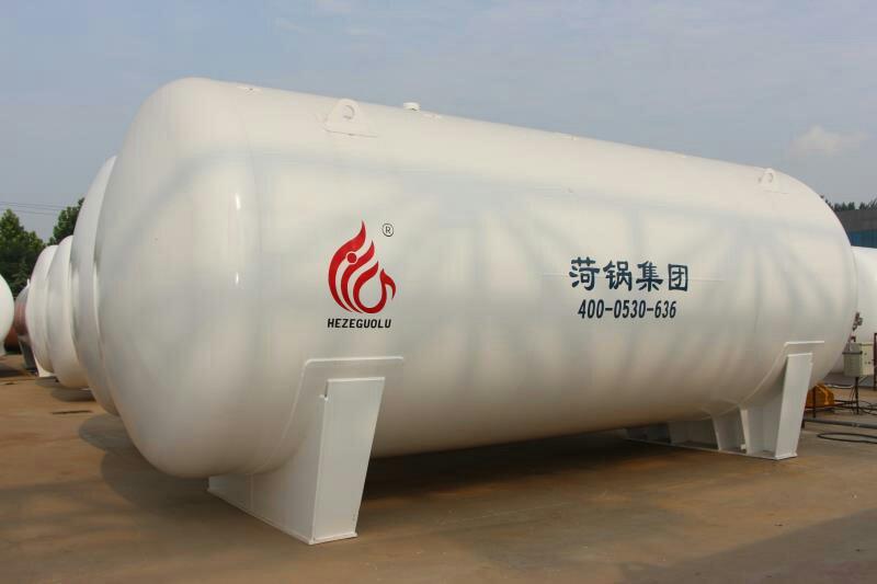
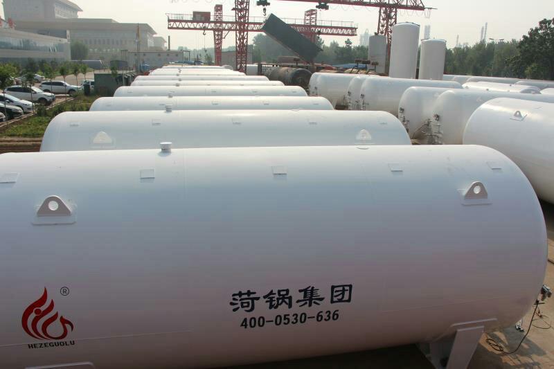
LNG Storage Tank
Tanks are the main equipment of LNG gasification stations, accounting for a significant portion of the construction cost. Great emphasis should be placed on tank design.
1.1 Material Selection for LNG Tanks
During normal operation, the working temperature of the LNG tank is -162.3°C, and it must be pre-cooled to -196°C prior to first use.
Liquid nitrogen pre-cools the tank, which is designed to operate at -196°C. The inner tank must withstand both the working pressure of the medium and the low temperature of LNG, requiring the inner tank material to have excellent comprehensive mechanical properties at low temperatures, particularly good low-temperature toughness. Therefore, the inner tank material is made of 0Crl8Ni9, equivalent to ASME (American Society of Mechanical Engineers) standard 304.
As a constant-temperature, external-pressure vessel, the outer shell is made of low-alloy steel Q345R, carbon steel Q245R, and Q235B.
1.2 Assume Design Responsibility
Tappings on the inner tank of the storage tank include: liquid inlet at the top, liquid inlet at the bottom, liquid outlet, vapor phase outlet, fullness measuring port, upper level gauge port, lower level gauge port, and 8 process manholes. The materials of the tappings on the inner tank are all 0Cr18Ni9.
To facilitate regular measurement of vacuum levels and evacuation, a vacuum evacuation port is provided on the bottom sealed cap of the outer cylinder (the port is sealed after evacuation). To prevent vacuum failure and the leakage of the inner cylinder medium into the outer cylinder, a pressure relief device is installed on the sealed cap of the outer cylinder.
2. Truck Unloading Booster Vaporizer
Due to the absence of pressure boosting equipment on the LNG tank trucks, an onboard booster gasifier with a gasification capacity of m3/h is installed to increase the tank truck pressure to 0.6 MPa. The temperature of the LNG entering the gasifier is -162.3°C, and the temperature of the gaseous natural gas exiting the gasifier is -145°C.
3. Storage Tank Pressure VapORIZER
After filling a 100m3 LNG storage tank with 90m3 of LNG, calculate the pressure increase of the 10m3 gas phase space from the unloading state of 0.4MPa to the working state of 0.6MPa within 30 minutes. According to the calculation results, each tank requires one 200m3/h air-temperature gasifier for tank pressurization. The temperature of LNG entering the pressurized gasifier is -162.3°C, and the temperature of the gaseous natural gas exiting the pressurized gasifier is -145°C.
Designs often feature one LNG tank paired with one booster gasifier. Multiple tanks can also share a single or a set of gasifiers for boosting, which can simplify the process, reduce equipment, and lower costs through valve switching.
4. Air-temperature type vaporizer
The vacuum gasifier is the main gasification facility for city gas supply at LNG gasification stations. The gasification capacity of the gasifiers is determined based on the peak-hour gas consumption, with an allowance for excess capacity, usually set at 1.3 to 1.5 times the peak-hour gas consumption. They are grouped in sets of 2 to 4, with 2 to 3 sets designed for alternating use.
5. Water Bath Vaporizer
When the ambient temperature is low and the gas temperature at the outlet of the air-temperature gasifier is below 5℃, a water bath natural gas heater is connected in series after the air-temperature gasifier to heat the natural gas after gasification [5, 6]. The heating capacity of the heater is determined at 1.3 to 1.5 times the peak hour gas consumption.
6. BOG Heater (Boil Off Gas)
The essence is an air-temperature vaporizer.
Due to the largest BOG volume occurring after unloading from the recovery tank trucks, the design capacity of the BOG air-temperature heater is calculated based on this, with the time for unloading the gas phase natural gas from the tank trucks set at 30 minutes. Taking a 40m³ tank truck with a pressure drop from 0.6MPa to 0.3MPa as an example, the required capacity of the BOG air-temperature gasifier is calculated to be 240m³/h. Generally, the BOG air-temperature heater is selected based on the number of tank trucks that can be unloaded simultaneously at the gasification station. Typically, the heating capacity of the BOG heater ranges from 500 to 1000m³/h. During winter, the BOG is used as fuel for the hot water boiler in the water bath natural gas heater, while the rest of the year it is sent into the city's transmission and distribution network.
7. BOG Buffer Tank
For peak-shaving type LNG regasification stations, to recover excess gas from unloading tankers during off-peak periods and BOG (Boil Off Gas) from storage tanks, or for natural gas blending stations to achieve uniform blending, a BOG buffer tank is often added at the outlet of the BOG heater. The capacity of the tank is set according to the recovered excess gas from tankers.
8. Safety Discharge Gas (EAG) Heater
The EAG air-temperature heating equipment capacity is calculated based on the maximum safe venting volume of a 100m³ storage tank. The calculated safe venting volume for the 100m³ tank is 500m³/h, and a single air-temperature heater with a gasification rate of 500m³/h was selected in the design. The incoming gas temperature to the heater is -145°C, and the outgoing gas temperature is -15°C.
9. Pressure Regulating, Metering, and Odorization Equipment
Select pressure regulating devices based on the scale of the LNG gasification station. Typically, two pressure regulating devices are installed, with self-contained regulators equipped with a controller and overpressure cutoff selected as the regulators.
The measurement is carried out using a turbine flow meter. The odorant used is tetrahydrothiophene, and it is injected into the gas pipeline using a diaphragm metering pump as the power source, based on the flow signal.
10. Filter
Filter structural features
The station uses a mesh core filter for filtering out particulate impurities and water from the outgoing natural gas. The filter cores are replaceable, and the removed cores (made of stainless steel mesh) can be reused after cleaning. The filter is equipped with a pressure differential gauge, indicating the pressure difference between the inlet and outlet of the filter's gas, which represents the degree of clogging of the filter cores. The precision of the filter cores is generally selected as 50um, and the volume of the water collection chamber is greater than 12% of the filter's volume.


