


Liquefied Natural Gas (LNG) Storage Vessel Capacity and Applicable Scenarios
1. 60-cubic-meter LNG vacuum powder-insulated storage tank, available in sizes from 5 to 200 cubic meters. Suitable for residential gasification stations, industrial gasification stations, LNG refueling stations, small portable liquefaction units, and refrigerant storage, etc.
2. Mother-and-child horizontal low-temperature storage tanks, ranging from 300 to 5,000 cubic meters, suitable for small liquefaction units, air separation units, civil gasification stations, industrial gasification stations, and LNG gasification stations, etc.
3. Spherical Horizontal Low-Temperature Storage Tanks, 100 to 10,000 cubic meters, suitable for small and medium-sized liquefaction units, peak-shaving liquefaction units, air separation units, LNG storage and distribution stations, LNG gasification stations, etc.
4. Vertical flat-bottomed cylindrical storage tanks, ranging from 200 to 200,000 cubic meters, suitable for various liquefaction units, LNG storage and distribution stations, LNG regasification stations, air separation units, liquid hydrocarbon storage, and coastal LNG receiving stations.
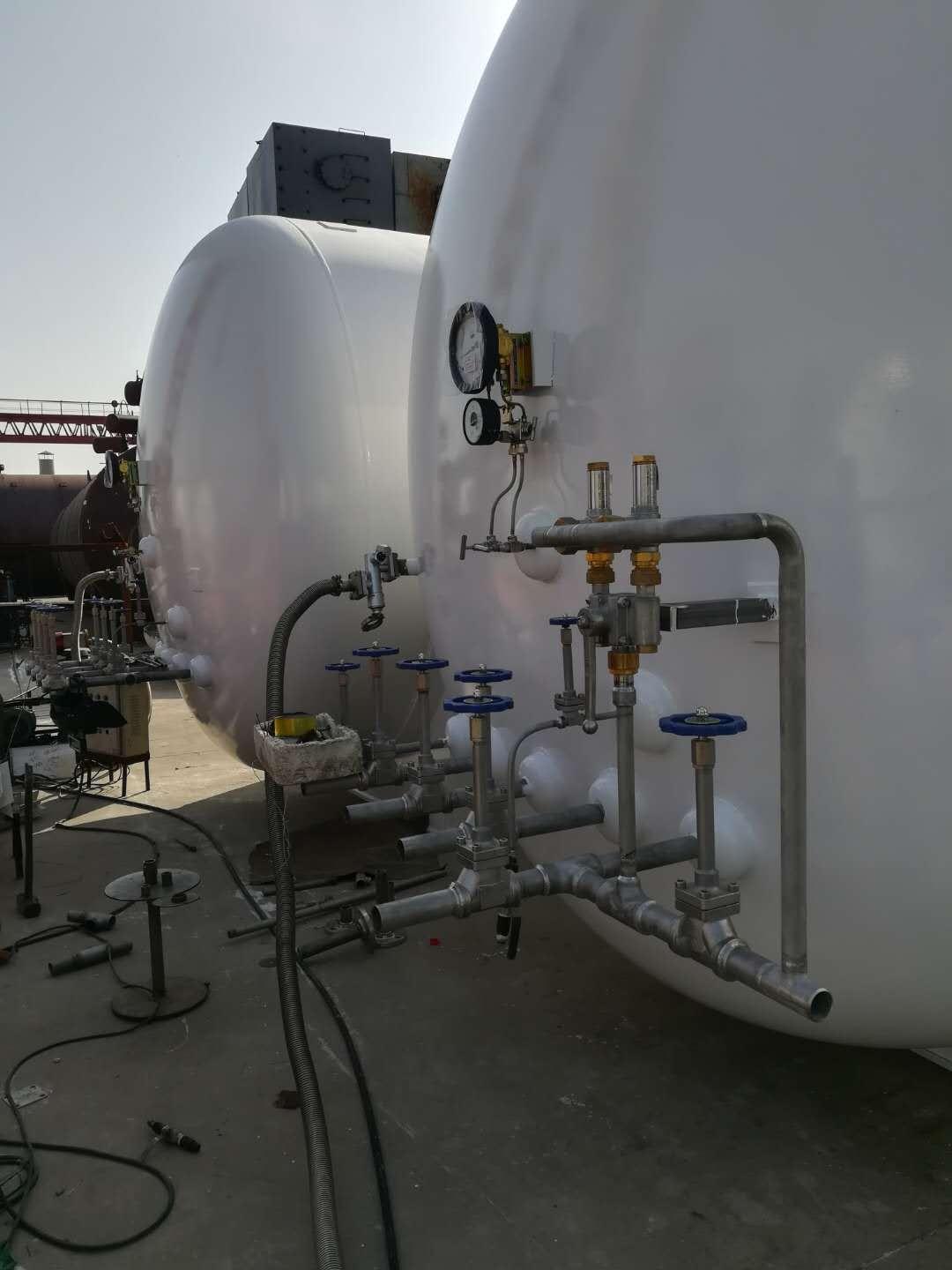
Vacuum powder insulation storage tanks consist of an inner cylinder and an outer cylinder, with the annular space insulated using vacuum powder insulation technology. Due to transportation constraints, the maximum tank capacity is currently 200 m³, and they are commonly used for storing smaller liquid volumes.
When the liquid storage capacity exceeds 200 m³, a 60-cubic-meter LNG storage tank can be connected in parallel as a cluster tank using multiple vacuum powder insulation storage tanks. When the storage capacity exceeds 1500 m³, it is advisable to use a horizontal sub-parent storage tank (abbreviated as sub-parent tank), which, compared to the cluster tank, offers advantages such as fewer site equipment, lower investment, convenient operation and maintenance, and safety and reliability. The sub-parent tank consists of multiple (more than 3) sub-tanks in parallel to form the inner tank, and a large outer tank (parent tank) is assembled. The sub-parent tank is also limited by transportation and lifting conditions, with a maximum single tank capacity of 250 m³ and a total maximum capacity of 5000 m³. When the storage capacity exceeds 200 m³, spherical horizontal low-temperature storage tanks and vertical flat-bottomed cylindrical horizontal low-temperature storage tanks can also be chosen. When the storage capacity exceeds 10,000 m³, horizontal flat-bottomed cylindrical low-temperature storage tanks are more commonly used. During the actual selection process, when the storage capacity is less than or equal to 200 m³, a vacuum powder insulation storage tank with mature manufacturing and installation technology is chosen for the 60-cubic-meter LNG storage tank.
LNG Gasification Plant Main Equipment
LNG Storage Tank
Tanks are the main equipment of LNG liquefaction plants, accounting for a significant portion of the construction cost. Great emphasis should be placed on tank design.
1.1 Material Selection for LNG Tanks
During normal operation, the working temperature of the LNG tank is -162.3°C; it must be pre-cooled to -196°C before the first use.
Liquid nitrogen pre-cools the tank, requiring the tank to be designed for a temperature of -196°C. The inner tank must withstand both the working pressure of the medium and the low temperature of LNG, necessitating that the inner tank material possess excellent overall mechanical properties at low temperatures, particularly good low-temperature toughness. Therefore, the inner tank material is selected as 0Cr18Ni9, equivalent to ASME (American Society of Mechanical Engineers) standard 304.
As an atmospheric pressure vessel at room temperature, the outer shell material is selected from low-alloy structural steel Q345R, low-carbon steel Q245R, and Q235B.
1.2 Takeover Design
Tapped openings on the inner tank of the storage tank include: liquid inlet, liquid outlet, gas phase outlet, level measurement outlet, upper level gauge outlet, lower level gauge outlet, and 8 process manholes. The material of the taps on the inner tank is all 0Cr18Ni9.
For easy regular measurement of vacuum and evacuation, a vacuum evacuation port is provided on the bottom of the outer casing lid (the port is sealed after evacuation). To prevent vacuum failure and the leakage of the inner tank medium into the outer tank, a blast-proof device is set on the outer casing lid.
2. Offloading Pressure Vapourizer
Due to the absence of pressurization equipment on the LNG tank trucks, an onboard gasification regasifier with a capacity of m3/h is installed at the station to increase the tank truck pressure to 0.6 MPa. The temperature of the LNG entering the regasifier is -162.3°C, and the temperature of the gaseous natural gas exiting the regasifier is -145°C.
3. Storage Tank Booster Vaporizer
After filling a 100m³ LNG tank with 90m³ of LNG, calculate the pressure increase of the 10m³ vapor space from 0.4 MPa at the unloading state to 0.6 MPa at the operating state within 30 minutes. According to the calculation results, one 200m³/h capacity air-temperature vaporizer is selected for each tank to increase pressure, with the LNG entering the pressure vaporizer at -162.3°C and the gaseous natural gas exiting the pressure vaporizer at -145°C.
Designs often feature one LNG tank paired with one booster gasifier. Multiple tanks can also share a single or a set of gasifiers for boosting, which can simplify the process, reduce equipment, and lower costs through valve switching.
4. Air-temperature type gasifier
The air-temperature vaporizer is the main vaporization facility for LNG gasification stations to supply gas to the city. The vaporization capacity of the vaporizer is determined based on the peak-hour gas consumption, with a certain margin, typically set at 1.3 to 1.5 times the peak-hour gas consumption. They are grouped in sets of 2 to 4, with the design incorporating 2 to 3 sets for alternating use.
5. Water Bath Vaporizer
When the ambient temperature is low, and the outlet temperature of the air-cooled gasifier is below 5℃, a water bath-style natural gas heater should be connected in series after the air-cooled gasifier to heat the gasified natural gas [5, 6]. The heating capacity of the heater is determined as 1.3 to 1.5 times the peak hour gas consumption.
6. BOG Heater (Boil Off Gas)
The substance is an air-temperature vaporizer
Due to the largest BOG volume occurring after unloading of the recycling tank cars, the design capacity of the BOG air temperature heater is calculated based on this, with the time for unloading the gas phase natural gas from tank cars set at 30 minutes. For instance, with a 40m³ tank car pressure dropping from 0.6MPa to 0.3MPa, the required capacity of the BOG air temperature heater is calculated to be 240m³/h. Generally, the number of tank cars that can be unloaded simultaneously at the gasification station determines the selection of the BOG air temperature heater. Typically, the heating capacity of BOG heaters ranges from 500 to 1000m³/h. During winter, water bath natural gas heaters are used, with BOG serving as fuel for hot water boilers. For the rest of the year, it is sent into the city's transmission and distribution network.
7. BOG Buffer Tank
For peak-shaving LNG regasification stations, to recover surplus gas from off-peak unloading tanker trucks and BOG (Boil Off Gas) in storage tanks, or for natural gas blending stations to achieve uniform blending, a BOG buffer tank is often added at the outlet of the BOG heater. Its capacity is set according to the recovered gas volume from the tanker trucks.
8. Safety Discharge Gas (EAG) Heater
The EAG air temperature heater equipment capacity is calculated based on the maximum safe venting volume of a 100m³ tank. Calculations show that the safe venting volume of the 100m³ tank is 500m³/h, and a single air temperature heater with a gasification volume of 500m³/h was selected in the design. The entering gas temperature to the heater is -145°C, and the exiting gas temperature is -15°C.
9. Pressure Regulating, Metering, and Odorization Equipment
Select pressure reducing devices based on the scale of the LNG gasification station. Typically, a 2-way pressure reducing device is installed, with an automatic pressure reducing valve equipped with a controller and an overpressure cutoff function.
The measurement is carried out using a turbine flowmeter. The odorant used is tetrahydrothiophene, and the odorization is powered by a diaphragm metering pump, injecting the odorant into the gas pipeline based on flow signals.
Filter
Filter structural characteristics
The site uses a mesh core filter for filtering out particulate impurities and water from the outgoing natural gas. The filter cores are replaceable, and the removed cores (made of stainless steel mesh) can be cleaned and reused. The filter is equipped with a pressure gauge that indicates the pressure difference between the inlet and outlet gases, indicating the degree of clogging of the filter cores. The precision of the filter cores is generally 50um, and the volume of the water collection chamber is greater than 12% of the filter's volume.


