


液化天然气储罐厂家:
液化天然气储罐生产厂家:Heze Boiler Factory Co., Ltd.
I. LNG Tank Safe Operation Procedures
1.1.1 Storage Tank Operation Process Specifications
1)Highest AllowableWork Pressure: 0.86MPa
2)DesignTemperature: -196℃
1.1.2 Tank Liquid Filling Procedure
1.1.2.1 Preparations
1) Operator Requirements: Operators must be certified after undergoing safety education and operational technique training, and must wear necessary protective gear and work uniforms during operations.
2) Pressure Testing Requirements
3) All equipment should undergo pressure tests in accordance with design requirements prior to operation.
4) The test pressure gas should be dry nitrogen, with oxygen content not exceeding 3%, and moisture dew point not exceeding -25°C, and must be free of oil contamination.
5) Purge Replacement Requirements: Purge replacement is a safety measure to ensure the formal filling of equipment with liquid. It should first be purged with nitrogen containing no more than 3% oxygen, while ensuring no oil contamination and a dew point of no more than -25°C. Then, LNG should be used to replace the liquid to achieve the required purity before allowing the filling of the liquid.
6) Pre-cooling: After pressure testing passes, the equipment must be pre-cooled using liquid nitrogen to ensure reliable low-temperature operation. The tank must be purged and pre-cooled with nitrogen prior to its first use. The high purge pressure should be equivalent to 50% of the high working pressure, or lower than this pressure.
1.1.2.2 Initial Liquid Filling Operation of Storage Tank
1) Open both the upper and lower liquid inlet valves simultaneously for filling. At the same time, open the overflow valve for liquid filling and discharge the gas in the storage tank until LNG gas is discharged; immediately close the overflow valve for liquid filling.
2) When the tank is filled to over 50% of its volume, the lower liquid inlet valve should be closed.
3) When the tank is filled to 85% of its capacity, close the inlet valve and cease filling for 5 minutes to allow the liquid level to stabilize. Then, reopen the inlet valve and continue filling until liquid begins to overflow from the full flow valve. Immediately close the full flow valve, stop filling, and close the inlet valve.
4) Upon initiating fluid filling, loosen the fittings at both ends of the level gauge. Fully open the liquid phase indicator valve and the gas phase indicator valve to check if any moisture is present in the exhaust gas stream. If moisture is detected, continue to exhaust until no moisture is present. Then, tighten the fittings at both ends of the level gauge and close the balancing valve to place the level gauge in normal operating condition.
1.1.2.3 Tank Refueling Procedure
1) After the initial formal filling, the gas phase pressure inside the tank should be reduced as much as possible during subsequent refilling.
2) Fill both top and bottom simultaneously. When the liquid level gauge indicates approximately 50% full, close the lower inlet valve. When filled to 85% of the tank's capacity, close the upper inlet valve and stop filling for 5 minutes to allow the liquid level to settle. Then, reopen the upper inlet valve and continue filling until liquid starts to drain from the overflow valve. Close the overflow valve and simultaneously close the upper inlet valve to stop filling.
3) Monitor the pressure gauge and level gauge during filling. (If the pressure rises above the filling pressure or nears the safety valve pressure, it is necessary to open the gas exhaust valve to release an appropriate amount of gas phase from the storage tank.)
4) Fill out the Operation Record Sheet
2. Storage Tank Pressure Boosting Operation Procedure
1) The booster system is a pressure regulating system for the storage tank. When the tank pressure falls below the set value, we open the booster regulating valve to increase the pressure in the tank.
2) During operation, open the boost liquid phase valve to allow LNG to enter the boost gasifier directly. After vaporization, it passes through BOG and enters the storage tank. At this point, closely monitor the pressure, and close the boost liquid phase valve once the storage tank pressure reaches the desired level.
3) Cautionary Notes:
a) During operation, the LNG tank must maintain a liquid level of ≥15%.
b) During the operation of the boost system, personnel are strictly prohibited from leaving the site.
c) When the supercharging system is in operation, the decompression system should be turned off.
3. Tank Discharge Operation Procedure
Preparation Work:
1) Check that the tank's pressure gauge, level gauge, thermometer, flammable gas detector, and safety valve are operating normally.
Check if the pipeline valves, pressure gauges, and safety valves are in normal working condition.
3) Prepare all explosion-proof tools and wear protective gear.
Section II: Catalytic Converter Safe Operating Procedures
1) First, close the in-liquid and out-liquid valves in the system, then slowly open the in-liquid valve. When frost forms on the pipes, gradually open the exhaust valve until the required vaporization amount is achieved, then stabilize the valve opening.
2) If frost is found on the exhaust pipe, indicating an excessively low exhaust temperature, it suggests an excessive amount of liquid intake. It is imperative to immediately reduce the intake valve to prevent overflow, and frost on the pipe exterior should be cleared promptly. Increase ventilation equipment or take other appropriate measures.
3) The vaporizer must be oil-free. When operating, wear oil-free insulated gloves. If the vaporizer is confirmed to be contaminated with oil, the heat exchanger should be cleaned. It can be washed with hot water at 60-80°C, and if necessary, nitrogen heated to 80-100°C should be used for blowing. Continue until it is confirmed to be oil-free and dry.
4) In severe cases, use carbon tetrachloride for cleaning. Be highly alert during cleaning and wear a gas mask if the odor is intense. After the chemical solution is washed off, rinse with oil-free and debris-free water until no chemical components are present in the water. Then, use nitrogen heated to 80-100°C to blow off the moisture, and confirm that it is completely dried.
5) Conduct semi-annual leak checks on the evaporator and the entire pipeline system, and keep detailed records.

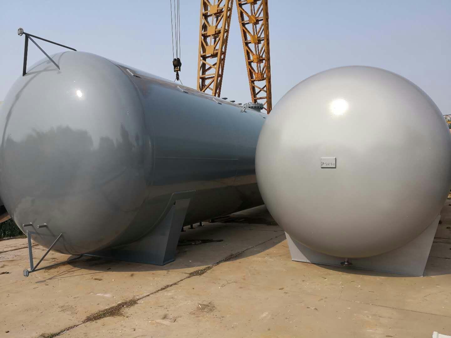
Liquefied Natural Gas Storage Tank
Low-temperature Liquefied Natural Gas (LNG) Storage Tanks, Manufacturer of LNG Storage Tanks:Huzhou Boiler Factory Co., Ltd., Manager Yu。
LNG above-ground storage tanks come in five forms: the single-container type is commonly used, dividing into single-walled and double-walled tanks. Due to safety and insulation considerations, single-walled tanks are not used for LNG storage. The outer shell of the double-walled single-container tank is made of ordinary carbon steel, unable to withstand the low temperatures of LNG or the low-temperature gases, primarily serving to secure and protect the insulation layer. Single-container tanks are generally suitable for use in areas far from densely populated regions and less prone to catastrophic damage, requiring significant safety distances and land area due to their structural characteristics. The design pressure for single-container tanks is typically kPa, with operating pressure at 12.5kPa. For large-diameter single-container tanks, the design pressure is correspondingly lower; according to the BS7777 standard, such tanks have a design pressure less than 14kPa, which is challenging to achieve when the diameter is 70-80m, with the maximum operating pressure around 12kPa. The lower design pressure necessitates a larger power requirement for the evaporation gas recovery and compression system, increasing investment and operational costs. While the investment in single-container tanks is relatively low and construction periods are shorter, leakage is a significant issue. In accordance with regulations, the safety distance between tanks is large, and firebreaks must be set up, thus increasing land and firebreak investment. There should be no other critical equipment nearby. Therefore, higher safety inspections and operational standards are required.
Liquefied Natural Gas (LNG) Storage Tanks, Low-Temperature LNG Storage Tanks, Manufacturer of LNG Storage Tanks:
Heze Boiler Factory Co., Ltd., Manager Yu。
(1) On the foundation of the storage tank, there is a trench with a depth of 1.5 em, length of 20,100 cubic meters (2014-7), for power distribution, grounding electrodes, as shown in Figure 3 (Electrolytic Ion Grounding Electrode), filled with clay for factory backfill, and as shown in Figure 4 (Electrolytic Submerged Grounding Electrode Installation), with a width of 2 meters (20 tons). (2) Wipe the grounding electrode clean with a dry cloth, ensuring no oil residue; inject clean water into the ion release holes at the top, middle, and bottom of the grounding electrode. (3) Mix the GAF powdered grounding enhancer with water, then place it at the bottom of the trench. (4) Position the grounding electrode at a certain angle on the bottom of the trench, covering the top with the enhancer. (5) Wrap the grounding electrode leads with insulating tape and connect them to the grounding main using a hot melt welding method. 5 Static Grounding Setup When LPG is injected into the storage tank, the liquid flow causes charge separation, and when the charges accumulate to a certain extent, static discharge occurs. Since static discharge is completed in the nanosecond range, the peak current can reach dozens of amperes, making the instantaneous power enormous, and the static discharge has severe destructive power. To avoid static hazards: 1) Limit the speed of the flammable liquid flow to greatly reduce the generation and accumulation of static electricity; 2) Ensure proper static grounding. Static grounding provides a path for the release of static charges through grounding. The grounding circuit must be reliably connected; otherwise, spark discharges will occur at points of poor contact. The specific method is: weld grounding bolts to the inner wall of the storage tank, connect them to the outer metal body through a 70 mm² insulated copper core wire to release static electricity. The static grounding connection is shown in Figure 5. Figure 5 Static Grounding Connection Wall 6 Grounding Test Results According to GB 50057-2010, Article 4.3.10, the impact grounding resistance value at each grounding point should not exceed 30 ohms. According to GB 12158-2006, "General Guidelines for Preventing Static Electricity Accidents," Article 6.1.2, to dissipate static charges as quickly as possible in static hazardous areas, all objects that are static conductors must be grounded. The grounding resistance value of each dedicated static grounding body generally should not exceed 100 ohms. In areas with high soil resistivity, such as 100 ohm zones, the grounding resistance value should also not exceed 1,000 ohms. After the lightning protection grounding project is completed, the measured grounding resistance value is 0.8 ohms, and the grounding leads are well connected to the grounding main, meeting the lightning protection grounding requirements.
LNG storage tanks, low-temperature LNG storage tanks, manufacturer of LNG storage tanks:
Heze Boiler Factory Co., Ltd., Manager Yu。
Current transformer secondary circuit open circuit differential protection. Select via control words whether to lock the differential protection output when the current transformer secondary circuit is open-circuited and the differential current is not significant. When the current transformer secondary circuit is open-circuited and the differential current is low, the differential protection device emits an alarm signal, notifying the dispatch personnel to shut down the transformer for maintenance by reversing the load. This action can prevent the main transformer from tripping due to the secondary circuit open-circuit of the current transformer. If the differential current increases to the open-circuit differential protection setting (usually the rated current of the transformer, P), then activate the open-circuit differential protection. In this way, the transformer differential protection operates, the main transformer trips, and the protective device can correctly disconnect the fault current, preventing the accident from escalating. This can be considered a compromise solution, balancing the advantages and shortcomings of the first two methods, achieving a good effect. For the 110 kV substation No. 1, transformer No. 3 (capacity 63 MVA, voltage ratio 110 kV/10.5 kV, connection type YNdll, primary current transformer ratio 600 A, secondary current transformer ratio 4000, the differential protection settings are as follows: differential quick-break current setting, ..=4.4 (A), differential protection start setting, ..=0.28 (A), ratio braking coefficient setting K=0.5, second harmonic braking coefficient 0.15, open-circuit differential protection setting 0.8. On a certain day at 06:42, an alarm was reported at the No. 1 substation back-end, indicating that the secondary circuit of the differential protection current transformer for transformer No. 3 was open-circuited, with a sudden change in current of 0.08 A and a phase difference differential current of 0.056 A. After contacting the dispatch personnel to reverse the load and shut down the power, the equipment was inspected and found to be loose terminal blocks on the SF6 enclosed switchgear. After tightening the terminal blocks, the fault was eliminated.


Custom-made LNG Tank Wholesale - Where to Find LNG Tank Brands - Professional LNG Tank Fabrication Services - Renowned LNG Tank Models
