


Heze Boiler FactoryLimited Company

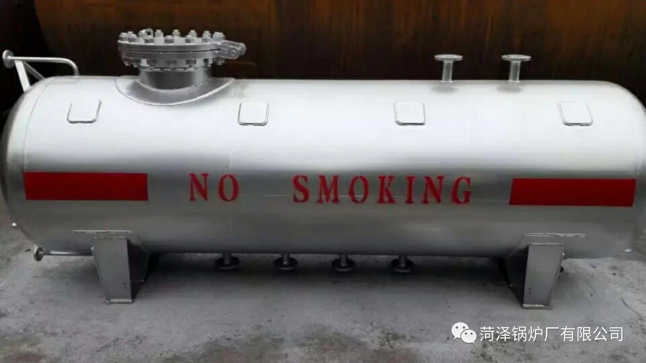
60 cubic meters LNG storage tank
Product Category: LNG Storage Tanks
LNG stands for Liquefied Natural Gas. Its primary component is methane. LNG is colorless, odorless, non-toxic, and non-corrosive. Its volume is approximately 1/600th that of an equivalent volume of gaseous natural gas, and its weight is about 45% of the same volume of water. Its calorific value is around 52 MMBtu per ton (1 MMBtu = 2.52×10^8 calories).
Model:
60 cubic meters0.8MPa
Detailed Introduction
【Product Name】: LNG Storage Tank
Manufacturer:Huzhou Boiler FactoryLimited Company
LNG Storage Vessel
He Guo Group
An LNG storage tank is a jacketed vacuum powder-insulated pressure vessel specifically designed for storing and supplying low-temperature liquefied gases (such as liquid nitrogen, liquid oxygen, liquid argon, liquid carbon dioxide, etc.). It has been widely used in both industrial production and daily life. This article briefly outlines the basic requirements and safety usage points by analyzing the hazardous characteristics of low-temperature liquids and combining them with various gas supply modes for low-temperature liquid storage tanks.
1. Analysis of Low-Temperature Liquid Hazardous Characteristics
Low-temperature liquids possess hazardous characteristics such as lower boiling points, greater expansibility, strong asphyxiating properties, and strong oxidizing properties.
1.1 Boiling points of low-temperature liquids at 101.3 KPa pressure: Liquid nitrogen at -196°C, liquid oxygen at -183°C, and liquid argon at -186°C. Contact with the human body can cause severe frostbite to the skin and eyes. In cases of minor leakage or internal leakage in valves and pipes, these liquids absorb heat from the surrounding environment, causing rapid condensation and frost formation at the leakage point, which may lead to freezing in severe cases.
1.2 Low-temperature liquids absorb energy from the surrounding environment due to high heat or large leaks, causing their volume to expand rapidly upon vaporization. Under 0℃ and 101.3 KPa pressure, the volume of gases produced from 1L of low-temperature liquid vaporization is: nitrogen 674L, oxygen 800L, and argon 780L. Inside sealed containers or pipelines, the increase in internal pressure due to the vaporization of low-temperature liquids can easily lead to overpressure explosions.
1.3 In the environment surrounding the low-temperature liquid storage tank, the liquid can easily vaporize upon leakage, forming a rich gas area. If the concentrations of nitrogen, argon, or carbon dioxide are high, asphyxiation injuries can occur. Additionally, oxygen-rich injuries can also occur when the oxygen concentration is high.
1.4 Oxygen is a strong oxidizer with a highly reactive nature. When liquid oxygen is in close proximity to combustible materials, it can easily ignite upon contact with an open flame. It is prone to cause explosions due to vibrations or impacts when in contact with combustibles. Mixing it with combustibles poses a potential explosion hazard. Liquid oxygen can adhere to clothing and fabrics, and upon contact with an ignition source, it can cause a flash fire, posing a risk to personal safety.
2. Low-Temperature Liquid Storage Tank Gas Supply Mode and Basic Requirements
Based on different application scenarios and user requirements, the gas supply modes for low-temperature liquid storage tanks are primarily...
Available services: high-pressure gas cylinder refilling, low-temperature insulated gas cylinder packaging, centralized gas supply through pipelines, and low-temperature liquid spray supply.
LNG60 cubic meters @ 0.8 MPa parameter value:
60 cubic meter LNG storage tank
Formed:
The natural gas produced from the gas field is first purified and then liquefied under ultra-low temperature (-162℃) and atmospheric pressure to form liquefied natural gas.
The critical temperature of LNG between gas and liquid phases at atmospheric pressure is -162℃.
The standard commonly used in LNG manufacturing is API 620 of the American Petroleum Institute.
LNG Storage Vessel
Powered by low-temperature liquid storage tanks as the gas source, suitable for filling high-pressure gas cylinders, and ideal for numerous applications.
Individual users of scattered gas generally require standardized implementation by professional production and filling units. According to current national administrative permit requirements, filling units must hold a designated production (storage) approval for hazardous chemicals, a safety production license, and a gas cylinder filling license, collectively known as "one document and two licenses," to carry out high-pressure gas cylinder filling. At the liquid outlet of low-temperature liquid storage tanks, low-temperature liquid pumps and high-pressure gasifiers are installed, and a high-pressure filling system is used to fill high-pressure gas into specialized gas cylinders. In the gas cylinder filling process, a pipeline low-temperature and over-pressure automatic shutdown protection system must be set up. If there is still low-temperature liquid at the gasifier outlet or if the pipeline pressure exceeds the high working pressure of the gas cylinder, the low-temperature liquid pump should automatically shut down, and the low-temperature liquid storage tank should stop supplying gas to prevent the direct filling of low-temperature liquid into the gas cylinder or over-pressurization during filling, which could cause an explosion.

Operation Instructions
1. Utilize Security Management
(1) The user unit shall, in accordance with regulations, apply for and obtain a "Special Equipment Use Registration Certificate" from the department responsible for special equipment use registration at the location within 30 days before or after the product is put into use.
(2) Users shall comply with the relevant requirements of the "Special Equipment Operation and Management Regulations" to implement safety management for this product. This includes appointing a safety management supervisor, safety personnel, and operational staff, establishing various safety management systems, drafting operational procedures, and conducting inspections.
2. Pre-Use Preparation
Tanks and associated piping are installed and placed in position. After passing the acceptance inspection, prepare for pre-operation.
Tanks must be purged with dry nitrogen and pre-cooled with liquid nitrogen prior to first use. The purge pressure should not be less than 0.2 MPa.
Before blowing, loosen the connections at both ends of the differential pressure (level) gauge, and fully open the combination valve A9 of the differential pressure (level) gauge. Check if there is moisture in the exhaust air flow. If there is moisture, continue blowing until there is no more moisture. Tighten the connections at both ends of the differential pressure (level) gauge, and close the balancing valve to put the differential pressure (level) gauge into normal operating condition.
Prior to the first filling of the tank with LNG, replace the liquid nitrogen or nitrogen in the tank with LNG gas. First, open the drain valve A-6 to vent the nitrogen, then close the valve. Open the vent valve A-12 and transfer the LNG gas from the tank container into the tank via the unloading platform. When the tank pressure reaches 0.1-0.2 MPa, close the vent valve A-12, stabilize for 3 minutes, and then open the drain valve A-6 to vent. Repeat this process 2-3 times to complete the replacement. Use a flammable gas detector or take air samples for ignition tests to check the replacement extent.
During the first LNG filling, the tank should be pre-cooled or check the pre-cooling status of the tank previously. The liquid filling rate must be strictly controlled and operated slowly. First, slowly open the upper filling valve A-2, and transfer LNG from the tanker to the tank through the unloading platform. Due to the lag in vaporization when LNG is transferred into the tank, closely monitor the rate of pressure increase inside the tank. The liquid filling amount must be minimal. When the pressure reaches 0.3 MPa, open the gas exhaust valve A-12 to depressurize, and close the upper filling valve A-2 if necessary. Pre-cool the tank through continuous filling and exhaust. After a period of controlled filling, when the tank pressure stabilizes and the liquid level gauge indicates a certain level, gradually increase the opening of the upper filling valve A-2 and open the lower filling valve A-1.
3. Initial Filling Operation for Storage Tank
(1) Open the upper and lower liquid inlet valves A-2 and A-1, filling simultaneously from top and bottom. During the filling process, monitor the differential pressure (level) gauge readings. Open the full indicator valve A-4, vent the gas in the storage tank, and immediately close the full indicator valve A-4 upon the release of LNG gas.
(2) Close the lower liquid inlet valve A-1 when the tank is filled to over 50% of its capacity.
(3) When the tank is filled to over 85% of its volume, close valve A-2 to stop filling and wait for 5 minutes to stabilize the liquid level in the container. Then, reopen valve A-2 to continue filling and open valve A-4 to indicate full. Close valve A-4 and valve A-2 immediately when liquid starts to flow from valve A-4, and stop filling.
4. Tank Refueling Procedure
(1) Upon the first formal filling of the tank, and during subsequent refills, the gas phase pressure within the tank should be reduced as much as possible.
(2) Fill both the upper and lower sections simultaneously. When the differential pressure (level) gauge indicates approximately 50% of the tank's capacity, close the lower inlet valve A-1. When filled to about 85% of the tank's capacity, close the upper inlet valve A-2, stop filling for 5 minutes to allow the liquid level in the container to stabilize. Then, reopen the upper inlet valve A-2 to continue filling and open the full indicator valve A-4. Continue filling until liquid starts to discharge from the full indicator valve A-4. Close the full indicator valve and simultaneously close the upper inlet valve A-2, then stop filling.
(3) Monitor the pressure gauge and differential pressure (level) meter during the filling process. (If the pressure rises above the filling delivery pressure or near the safety valve pressure, the exhaust valve A-12 must be opened to release an appropriate amount of gas from the storage tank to relieve pressure.)
(4) Fill out the operation record form.
5. Tank Pressure Increase Operation Procedure (Valves and equipment for this stage are to be provided and installed by the owner)
Using a supercharger can increase the pressure inside the tank, with the boost pressure controlled according to the draining requirements and not exceeding the tank's maximum working pressure. The boost system of this tank is controlled by a pressure regulator valve, with the product pressure adjustment range being 0.2 to 0.8 MPa. The boost operation procedure is as follows:
Check if the pressure gauge is in working condition.
(2) Confirm the boost system pressure regulator is turned on.
(3) Gently open the shutoff valve.
(4) Close the shut-off valve when stopping the drain to prevent an increase in tank pressure.
(5) Important Notes:
1) During operation, the LNG tank must maintain a liquid level of ≥15%.
2) When operating the boost system, safety must be observed, closely monitored, and personnel are strictly prohibited from leaving the scene without authorization.
6. Tank Pressure Reduction Procedure
Open valve A-12 to reduce the vapor pressure inside the storage tank to no more than the pressure set on the pressure regulating valve, then close valve A-12.
7. Tank Discharge Procedure
Check that the tank's pressure gauge, differential pressure (level) gauge, combustible gas detector, and safety valve are all in normal working condition.
(2) Inspect pipeline valves, pressure gauges, and safety valves for proper operation.
(3) Prepare all explosion-proof tools and wear protective gear.
(4) Inspect the IV line and open drain valve A-6.


供应LNG储罐批发-专用LNG储罐哪里有卖-哪里有LNG储罐生产商-LNG储罐厂家直销
