


LNG Storage Tank
LNG stands for Liquefied Natural Gas. Its primary component is methane. LNG is colorless, odorless, non-toxic, and non-corrosive, taking up about 1/600th the volume of its gaseous counterpart, and weighs approximately 45% of the same volume of water. Its calorific value is around 52 MMBtu per ton (1 MMBtu = 2.52 x 10^8 calories).
Model:
CFL-5/0.8,CFL-10/0.8,CFL-15/0.8,CFL-20/0.8,CFL-30/0.8,CFL-50/0.8,CFL-60/0.8,CFL-100/0.8,CFL-150/0.8...
CFW-5/0.8,CFW-10/0.8,CFW-15/0.8,CFW-20/0.8,CFW-30/0.8,CFW-50/0.8,CFW-60/0.8,CFW-100/0.8,CFW-120/0.8,CFW-150/0.8…

Low-temperature storage tanks are designed and manufactured in strict accordance with national standards, widely used for the storage and use of cryogenic liquids such as liquid oxygen, liquid nitrogen, liquid argon, liquid carbon dioxide, liquid natural gas, and liquid ethylene, featuring various working pressures and specifications. Equipped with unique high-vacuum insulation technology, they offer excellent insulation properties, long-term vacuum maintenance, and extremely low operating costs. Modular pipeline systems and high-configured components enhance the equipment's performance and durability while reducing maintenance costs, significantly boosting your competitive edge.
Introduction:
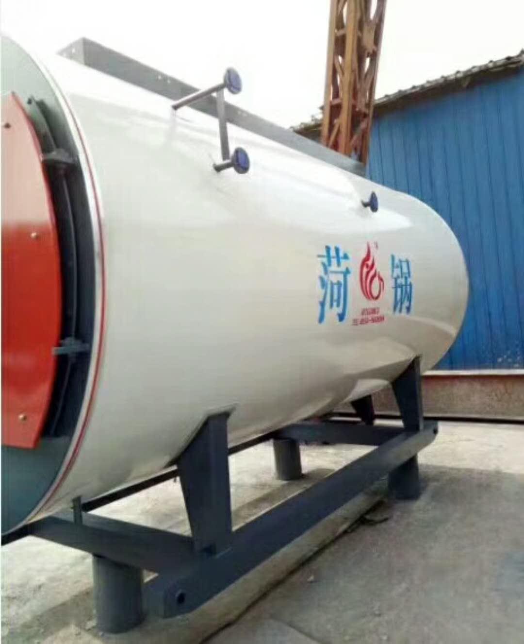
Low-temperature thermal insulation storage tanks are of vacuum powder insulation type, consisting of a double-container structure with an inner container and an outer container, which can be divided into vertical and horizontal types. The inner container, selected based on the medium it contains, is made of Austenitic stainless steel, specifically S30408. The outer container material varies according to the user's location, with Q345R being chosen. The interlayer between the inner and outer containers is filled with thermal insulation material, Pearlite sand, and then vacuumed.
Usage:
Storage of Liquid Oxygen (LO2), Liquid Nitrogen (LN2), Liquid Argon (LAr), Liquefied Natural Gas (LNG), Liquid Carbon Dioxide (LCO2)
Insulation performance:
Insulation materials are filled with pearl sand under heat and then evacuated. After the sandwich is sealed, the vacuum degree standard is:
Seal Vacuum Gauge
Design Parameters:
Design Pressure: 0.84 Mpa, 1.32 Mpa, 1.68 Mpa
Working Pressure: 0.8 MPa, 1.2 MPa, 1.6 MPa
Design Temperature: -196°C
Operating Temperature: -196℃
Effective Volume: 2.5m³, 3.5m³, 5m³, 10m³, 15m³, 20m³, 30m³, 50m³, 60m³, 100m³
Definition:
LNG stands for Liquefied Natural Gas.
The main component is methane. LNG is colorless, odorless, non-toxic, and non-corrosive, with a volume about 1/600th that of an equivalent volume of gaseous natural gas. Its weight is approximately 45% of the same volume of water, and its calorific value is around 52MMBtu/t (1MMBtu = 2.52×10^8 cal).
Formed:
The natural gas produced from the gas field is first purified and treated, then liquefied at ultra-low temperatures (-162℃) under atmospheric pressure to form liquefied natural gas.
The critical temperature of LNG between gas and liquid phases at atmospheric pressure is -162℃.
The standard commonly used in LNG manufacturing is API 620.
Meaning:
Liquefied Natural Gas (LNG) storage tanks are specialized products designed for storing liquefied natural gas, a type of special equipment.TwoPressure vessel category, 06Ni9DR material, completed with flaw detection, hydrostatic and pneumatic testing, on-site inspection by the Technical Supervision Bureau, issuance of pressure vessel inspection certificate, and external rust removal and painting processes. Liquefied gas storage tanks undergo strict quality assessment for the material of the pressure components, appearance dimensions, weld quality, operational quality, installation quality, internal equipment, and safety accessories.
Routine physical and chemical tests of the drum material, such as mechanical properties and chemical composition.
The weld joints, seams, tank ends, and the geometric positions of all pressure elements are rigorously inspected via X-ray non-destructive testing and magnetic particle inspection. Tests are conducted on the product's sealing, pressure resistance, and all technical indicators that could affect the safe operation of the product.
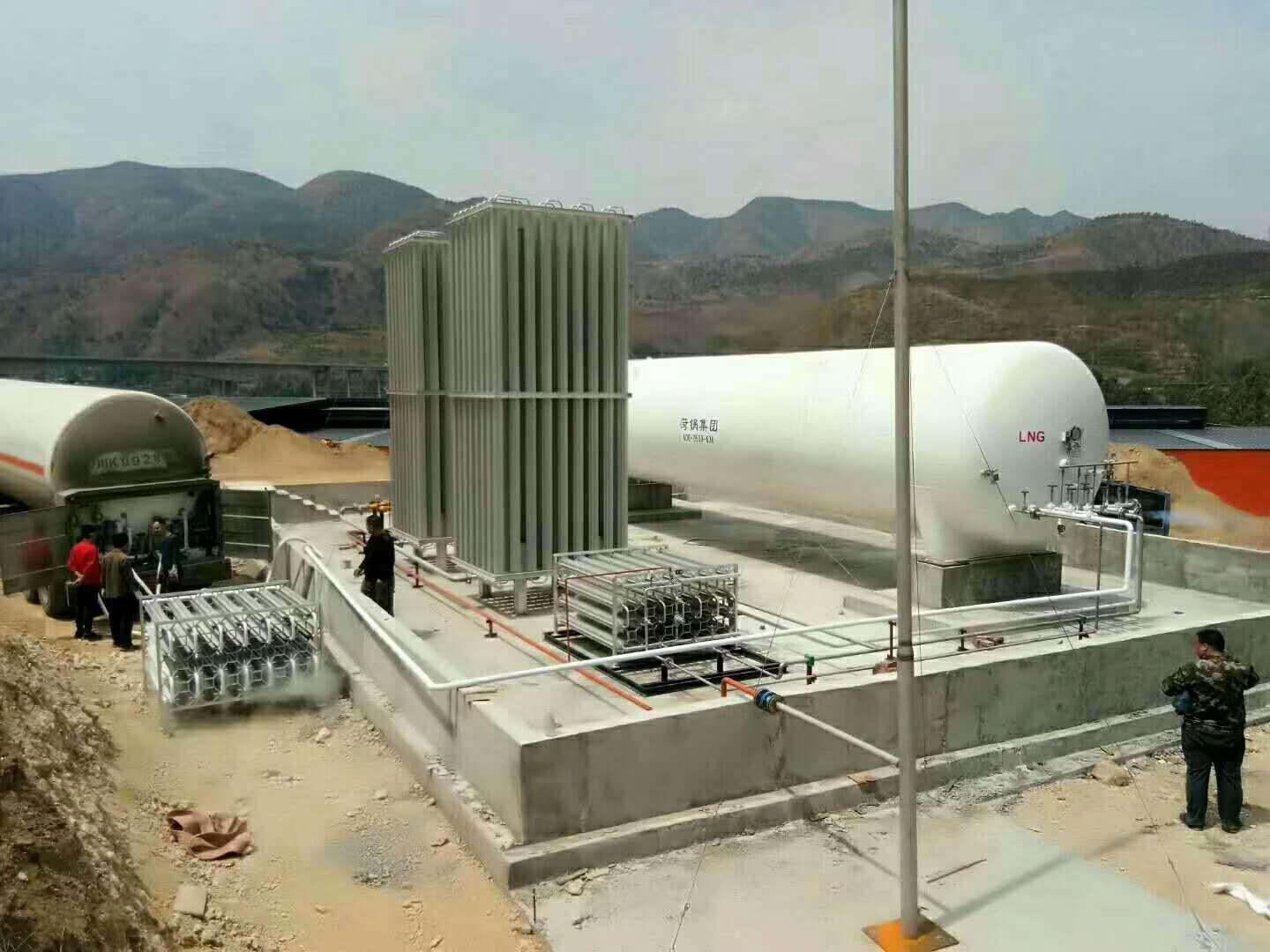
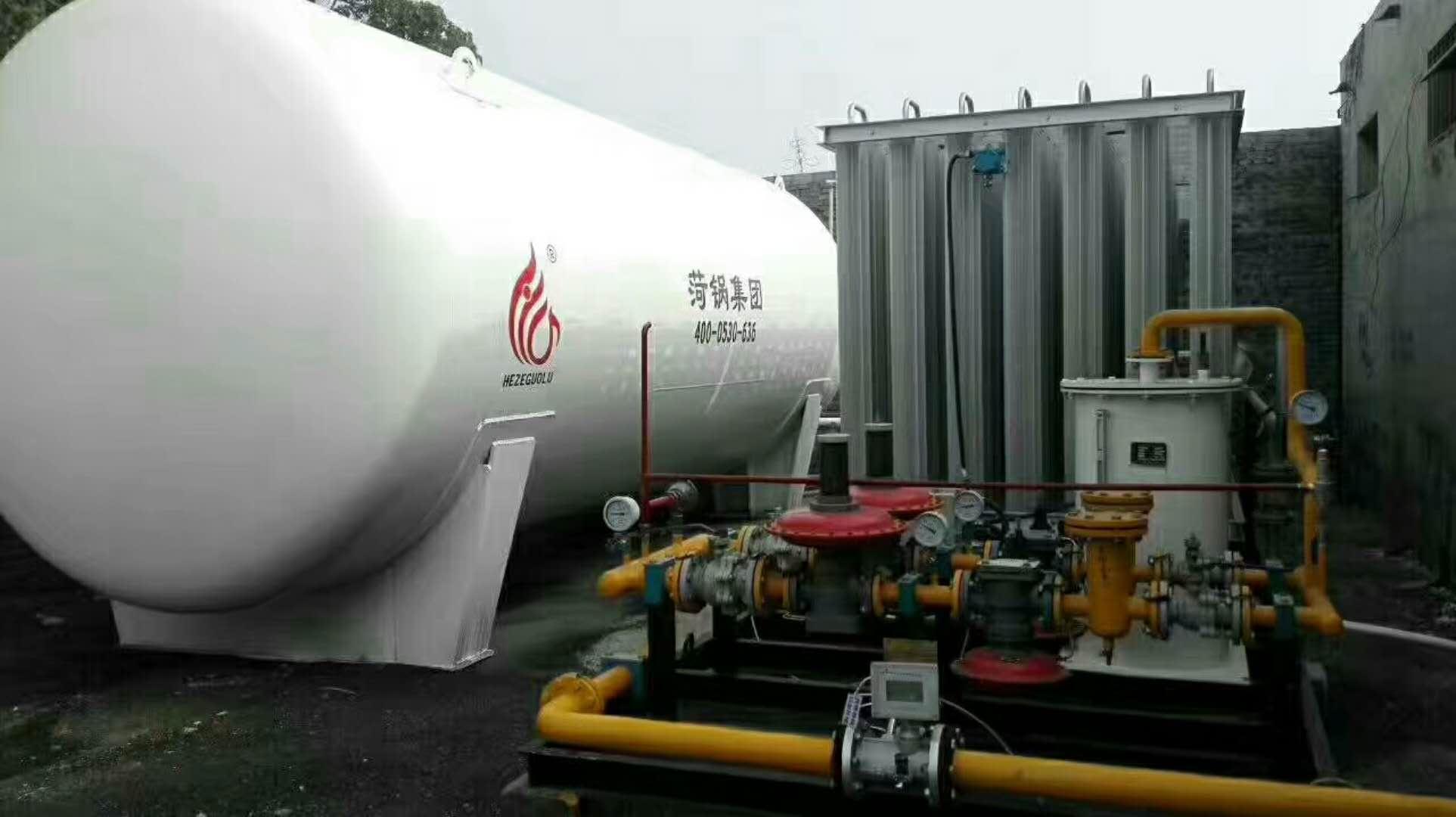
1. Natural Gas Storage Tank LNG Storage System: The LNG storage system consists of low-temperature storage tanks, auxiliary pipelines, and control instruments.
2. By capacity classification:
Small natural gas storage tanks, 5-50 cubic meters, commonly used in residential gas liquefaction stations, LNG vehicle refueling stations, etc.
Medium-sized natural gas storage tank, 50-100 cubic meters, commonly used in satellite liquefaction units, industrial gas vaporization stations, etc.
3. Natural gas storage tanks, LNG pipelines commonly use austenitic stainless steel pipes. Austenitic stainless steel pipes offer excellent low-temperature properties.
4. Vertical natural gas storage tanks, LNG storage tanks with vacuum powder insulation technology for heat insulation. The inner cylinder and pipeline materials are made of OCr18Ni austenitic stainless steel, and the outer cylinder is made of high-quality carbon steel Q345R pressure vessel steel plate. Our company offers a variety of storage tanks in sizes from 50 to 100 cubic meters.
5. Applications of Natural Gas Storage Tanks: Chemical fuel, residential fuel, automotive fuel, combined power generation, heat pumps, fuel cells, etc.
6. Natural Gas Storage Vessel Liquefaction Process: Cascade Liquefaction Process, Mixed Refrigerant Liquefaction Process, Liquefaction Process with Expander.
7. The natural gas storage tank liquefaction unit consists of pre-treatment process, liquefaction process, storage system, control system, and fire protection system, etc.

Operation Instructions
Utilize Security Management
(1) The using unit shall apply for and obtain the "Special Equipment Operation Registration Certificate" from the department responsible for special equipment operation registration at the location within 30 days before or after the product is put into use, as per regulations.
(2) Users should comply with the relevant requirements of the "Special Equipment Operation and Management Regulations" by implementing safety management for this product. This includes appointing a safety management supervisor, safety personnel, and operational staff, establishing various safety management systems, drafting operational procedures, and conducting inspections.
2. Pre-Use Preparation
Tanks and associated pipelines are installed and positioned; after passing the acceptance inspection, prepare for pre-use.
Tanks must be purged with dry nitrogen and pre-cooled with liquid nitrogen before initial use. The purge pressure should not be less than 0.2 MPa.
Before blowing, loosen the connections at both ends of the differential pressure (level) gauge, and fully open the combination valve A9 of the differential pressure (level) gauge. Check if there is moisture in the exhaust gas flow. If moisture is present, continue blowing until the moisture stops. Tighten the connections at both ends of the differential pressure (level) gauge, and close the balancing valve to put the differential pressure (level) gauge into normal working condition.
Before the tank is first filled with LNG, the liquid nitrogen or nitrogen in the tank should be replaced with LNG gas. First, open the drain valve A-6 to vent the nitrogen, then close the drain valve. Open the exhaust valve A-12 and transfer the LNG gas from the tank container to the tank through the unloading platform. When the tank pressure reaches 0.1-0.2 MPa, close the exhaust valve A-12, stabilize for 3 minutes, and then open the drain valve A-6 to vent. Repeat this process 2-3 times, and the replacement is complete. A combustible gas detector or air vent sample can be used for ignition tests to check the replacement extent.
During the initial LNG filling, the tank should be pre-cooled or checked for previous pre-cooling conditions. The inflow speed must be strictly controlled and operated slowly. First, slowly open the upper inflow valve A-2, and transfer the LNG from the tank car to the storage tank via the unloading platform. Due to the lag in vaporization when LNG is transferred to the tank, closely monitor the rate of pressure increase within the tank. Ensure the inflow amount is minimal. When the pressure reaches 0.3 MPa, open the gas exhaust valve A-12 to reduce pressure; if necessary, close the upper inflow valve A-2. Pre-cool the tank by continuously inflowing and exhausting. After a period of controlled inflow, when the tank pressure stabilizes and the liquid level indicator shows a certain level, gradually open the upper inflow valve A-2 wider and open the lower inflow valve A-1.
3. Initial Filling Operation for Storage Tank
(1) Open the upper and lower inlet valves A-2 and A-1, filling simultaneously from top and bottom. During the filling process, monitor the differential pressure (level) gauge readings. Open the full indicator valve A-4, vent the gas in the storage tank, and immediately close the full indicator valve A-4 upon the release of LNG gas.
(2) When the tank is filled to over 50% of its capacity, the lower liquid inlet valve A-1 should be closed.
(3) When the tank is filled to over 85% of its capacity, close the liquid inlet valve A-2, stop filling for 5 minutes to allow the liquid level in the container to stabilize, then reopen the liquid inlet valve A-2 to continue filling and open the full indicator valve A-4. Keep filling until liquid begins to flow from the full indicator valve A-4, then immediately close the full indicator valve A-4 and close the liquid inlet valve A-2 to stop filling.
4. Tank Refueling Operation Procedure
(1) After the initial formal filling, the gas phase pressure inside the tank should be reduced as much as possible during subsequent refilling.
(2) Fill both the upper and lower sections simultaneously. When the differential pressure (level) gauge indicates approximately 50% of the tank's capacity, close the lower inlet valve A-1. When filled to about 85% of the tank's capacity, close the upper inlet valve A-2. Stop filling for 5 minutes to stabilize the liquid level in the container. Then, reopen the upper inlet valve A-2 to continue filling, and open the full indicator valve A-4. Continue filling until liquid starts to discharge from the full indicator valve A-4. Close the full indicator valve and simultaneously close the upper inlet valve A-2, then cease filling.
(3) Monitor the pressure gauge and differential pressure (level) gauge during filling. (If the pressure rises above the filling conveying pressure or near the safety valve pressure, the exhaust valve A-12 must be opened to release a sufficient amount of gas from the tank to relieve pressure.)
(4) Fill out the operation record form.
5. Storage Tank Pressurization Operation Procedure (Valves and equipment for this section are provided and installed by the owner)
Using a supercharger can increase the pressure inside the tank. The boost pressure is controlled according to the draining requirements and must not exceed the tank's maximum working pressure. The boost system of this tank is controlled by a pressure regulating valve, with the product pressure adjustment range being 0.2 to 0.8 MPa. The boost operation procedure is as follows:
Check if the pressure gauge is in working condition.
(2) Confirm the boost system pressure regulating valve is open.
(3) Gradually open the bypass valve.
(4) When stopping the effluent, close the shut-off valve to prevent the tank pressure from rising.
(5) Important Notes:
1) During operation, the LNG tank must maintain a liquid level of ≥15%.
2) When operating the boost system, safety must be a priority, with strict monitoring and a strict ban on personnel leaving the site unauthorised.
6. Tank Pressure Reduction Procedure
Open valve A-12 to reduce the vapor pressure inside the storage tank to no more than the pressure set on the pressure regulating valve, then close valve A-12.
7. Tank Discharge Procedure
(1) Inspect the tank's pressure gauge, differential pressure (level) meter, flammable gas detector, and safety valve to ensure they are operating normally.
(2) Inspect pipeline valves, pressure gauges, and safety valves to ensure they are in normal operating condition.
(3) Prepare all explosion-proof tools and wear protective gear.
(4) Inspect the IV line and open the drain valve A-6.


Standard LNG Tank Models - Professional LNG Tank Contractors Available - Where to Buy Famous LNG Tanks - Price of Special LNG Tank Promotion
