


Tension-type Electronic Fence-Quick Installation Guide
Preface
This quick installation guide includes the following sections:Product AwarenessCabling GuidanceFence Installation GuidelinesCable Wiring Example
Note:Do not install electronic perimeter products outdoors during thunderstorms.Before installation, please carefully inspect the product's appearance, count the models and quantities of equipment and accessories, and if any anomalies are found, please contact our company immediately.Ensure safety education and technical training for installation personnel. Prior to the construction site, determine the installation location and method for the pulse main unit.Clear away debris (branches, greenery, etc.) adjacent to the perimeter, to avoid inconvenience during installation and to prevent interference with the normal operation of the front fence.Based on the on-site situation, work arrangements are being made.This manual may contain technical inaccuracies or printing errors. We will update this manual in accordance with changes in product functionality.The content of this manual, and we will regularly improve and update the hardware and software products described in this manual. Updated content will be available in the latest version of this manual.The update includes, no separate notification will be provided.The contents of this manual are provided for reference and guidance to users only and do not guarantee complete consistency with the actual product. Please refer to the physical product as the standard.
Product Introduction
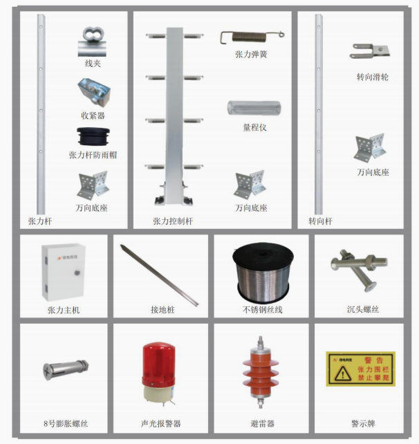
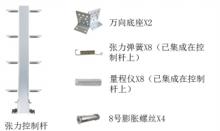
The main bill of materials is as follows:4 Please provide the Chinese content to be translated.
Cabling Guidelines
The Tension Fencing System consists of the front fence, tension control rod, tension main unit, rear control section, and other interlinked equipment.The Lijizhu main unit is the core for controlling, transmitting, and detecting the tension fence system, connected to the tension rod via a five-core wire and transmitting alarm signals.Transmitted to the backend control section for management. It is typically installed dispersedly within the perimeter, usually housed in an outdoor weatherproof box. The tension host through485 The bus connects to the control keyboard in a hand-in-hand manner. Each zone's length is40Within 1 mile.
Tension Host AdoptedAC220VPower supply, available for centralized or nearby locations.
Wiring Concept:
1Firstly, consider providing power to the equipment, which requires a power cord.(RVV)Recommend for useRVV2*1.0Cables with specifications equal to or greater than the above.
2Signal Transmission:
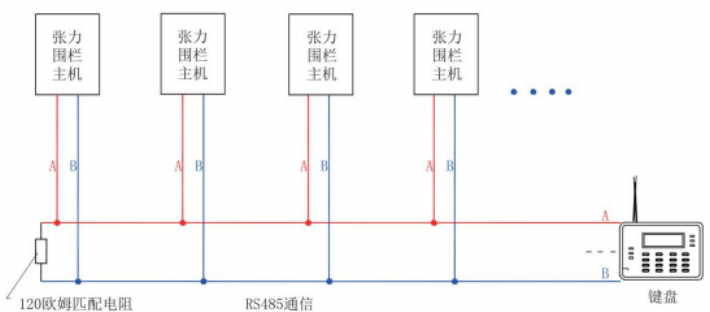
(1)Option 1: Signal transmission between the tension main unit and the next tension main unit is conducted via a bus system (hand-in-hand).,Connect to the backend controllerWiring for keyboard (alarm master unit) should be done with caution; ensure that the bus transmission length does not exceed1200Rice, recommend1000MiOptimal within, a single twisted pair signal cable can be used.(RVVSOrRVVSP)Please recommend for useRVVS2*0.75Spec-grade and above cables;
(2)Option Two: The tension main unit can be connected to the rear control keyboard (alarm main unit) via optical fiber.RS485No Chinese content provided.Connect the tension main unit with the rear control keyboard (alarm main unit) using fiber optic cable, and be mindful to leave at least one spare fiber optic core.
Cabling methods are as follows:
1. Excavating trenches along the bottom of the perimeter fence installation.30cmNo Chinese content provided, so the translation remains unchanged: "埋"2.0cmPVCTwo pipes (galvanized pipes are preferred), for signal lines,Cable routing.
2. The pipeline must leave an outlet opening at the tension main box.
3. SeededPVCAfter installation, use a punch to pass the power cable and signal cable through separately.PVCThe pipe is threaded to the tension host box, leaving a space.The segment length, from the pipeline mouth to the main unit, connects the main unit and extends back to the control room of the backend host.
4. During wiring, it is best to avoid junctions within the piping. If junctions are necessary, they should only be within the outlet ports.
5. PVCManagement buried underground30cmFor optimal performance, it is recommended to use Ф at locations with high traffic volume.50mmOur galvanized pipes, which are easy to bury underground.No content provided.50cm, Prevent communication failure caused by pipeline overload and damage.
6. If a pipeline reservation has been made, wiring can be done directly using a wire puller.
7. To save costs, power lines can be sourced locally. Signal lines should be connected around the perimeter to each server and then return to the server room to connect to the control system.Keypad (Alarm Control Unit).
8. Ensure sufficient distance between power cable conduits and signal cable conduits to avoid signal interference. Refer to national standards for wiring specifications.GB50311-2007。
Fence Installation Guide
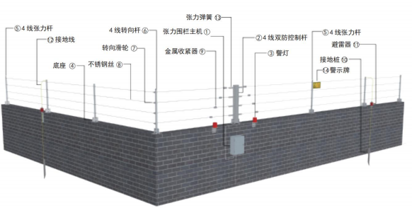
Tension fence installation primarily includes tension rods, tension cables, support rods, turning rods, stainless steel wire, tensioners, and warning signs.Labels, surge protectors, alarm systems, etc.
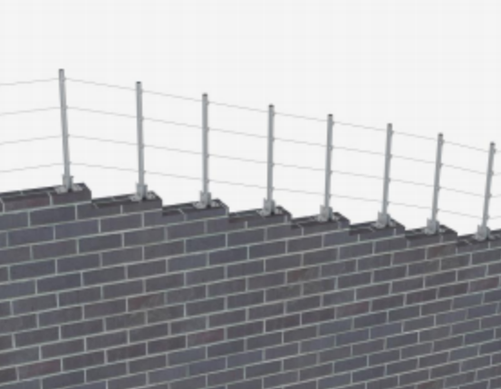
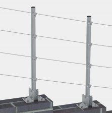
Front-end Fence Installation Structure Diagram:
Note:
Front-end fence components include tension rods, tension rod rain caps, swivel rods, swivel pulleys, universal bases, tension control rods.Comprising tension springs, metal tensioners, wire ropes, wire clamps, warning signs, lightning rods, sound-and-light alarms, and grounding rods, etc.
Installation Principles:
Recommend Tension Rods Every40m Install one; the actual installation on-site depends on the spacing of the fence piers, with the turning rod mounted at corners.Curves should be present, with specific spacing determined by the actual installation. A support rod is generally installed between the tension control rod and the tension rod.4-6 Install one meter.
A row of tensioners is installed in each defense zone, positioned close to the tension control rod for easy adjustment of the fence wire's tension.
The wire line is securely clamped at the starting, ending, or connecting points.
Caution signs every10m Install one.
Each surge arrester is installed in a separate zone, with a distance from the rainproof box of not less than10m。
Sound and light alarm units are mounted above the weatherproof boxes, with one per zone.
Please refer to the illustration above for the corresponding markings.,Please carefully read the following installation instructions and proceed with the installation steps.
1.1 Installation of Tension Rod
The tension rods are factory-assembled with springs and range gauges, typically mounted above the tension main unit.Primary Components of the Tension Rod
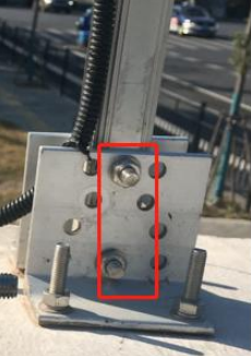
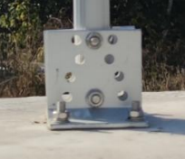
1.1.1 Insert the base into the through-bolts at the bottom of the tension rod and secure with nuts. The base is for2 Two on each side.
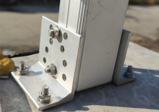
1.1.2 Please provide the Chinese content to be translated.8 Expansion bolts will securely fasten the tension rod of the base to the wall.
1.2 Installation of Tension Rods
Tension rods are typically installed at the end of the protective zone (i.e., the end farthest from the tension host).Key Components of the Tension Rod:
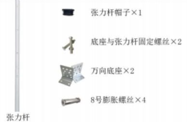
1.2.1 Secure both bases to the tension rod using the base and tension rod fixing screws, one on each side.
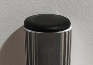
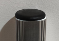
1.2.2 The tension rod hat is securely installed at the top of the tension rod.
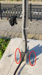
1.2.3 Please provide the Chinese content you would like translated into American English.4 No Chinese content provided, so no translation needed.8 Expansion bolts will secure the tension rods with a base and cap to the wall, with the orientation of the holes on the rod body...Direction of stainless steel wire is at an angle.90 No Chinese content provided.
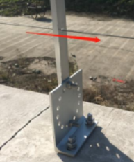
1.3 Installation of the support rod
Between the tension rod and the tension bar, a support rod is generally installed.4-6 Install one meter.Primary Components of the Support Rod
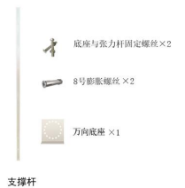
1.3.1 Secure one base to the support rod with the fixing screws provided. Typically, the base is mounted on the right side.
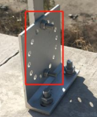
1.3.2 Please provide the Chinese content that you would like translated into American English.2 No Chinese content provided.8 Expansion bolts will be installed to secure the support rod with the base to the wall, aligning the direction of the holes on the rod with the stainless steel wire.Consensus Achieved.
1.4 Installation of steering rods
The steering rod is generally installed in areas with a bend.Steering rod main components
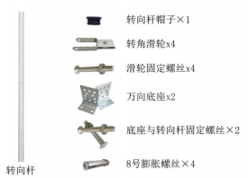
1.4.1 Secure the corner pulley to the steering rod with the included screws and nuts.
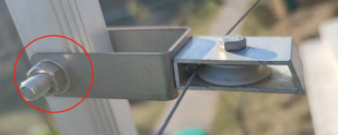
1.4.2 Secure the base and steering rod with the fixing screws.2 A base is mounted onto each steering rod, one on each side.
1.4.3 The tension rod cap is securely installed at the top of the steering rod.
1.4.4 Secure the assembled steering rod to the wall.
1.5 Installation of Stainless Steel Wire
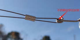
After all the rods are installed, stainless steel wire and tensioners are attached.1.5.1 The length of the stainless steel wire cut is generally the length of the protection zone plus...20-40cm。 1.5.2 At the end of the defense zone, at the tension rod, first thread the stainless steel wire through one of the holes in the clamps, then through the hole in the tension rod.Through the hole in the line clamp, securely fasten the clamp by using the tool to tighten it.
1.5.3 Then, sequentially pass the stainless steel wire through the holes in the support rods within the protection zone.
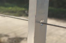
Stainless steel wire passes through the pulley at the steering rod.
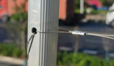
1.5.4 Through a support rod, at the tension control rod, stainless steel wire is threaded through the tensioner.3 A hole.
1.5.5 The stainless steel wire is threaded through the clamp and then through one of its holes, followed by passing it over the spring on the tension control bar on the outside.The hole is pierced again, and the wire clamp is securely fastened by tightening the tool through the hole in the clamp.
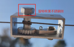
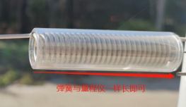
1.5.6 The rotating line tensioner tightens stainless steel wire until the spring length of the tension control rod matches the length of the range gauge.
1.5.7 Installation of varying altitudes
The working principle of the Tension Fencing is to detect the tension of the stainless steel wire, therefore, it requires the use of a rod with a pulley in areas with a drop.Ensure a smooth transfer of tension on stainless steel wire. In areas with differences in elevation, it is necessary to use the rod body of a directional rod.And the pulleys, which are directly mounted on the rod, are shown as follows.
The stainless steel wire at the pulley simply passes through the pulley itself.
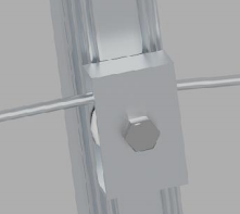
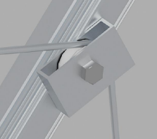
Small gapSignificant disparity
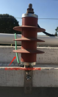
1.6 Surge protector installation
A lightning rod is installed in each defense zone, typically at the beginning or end of the front fence.1.6.1 The surge protector is securely fastened to the matching bracket with its own nuts.
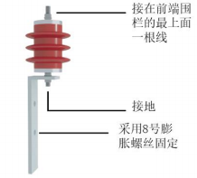
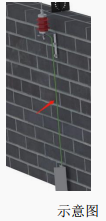
1.6.2 The lightning rod with mounted brackets is installed on the wall.
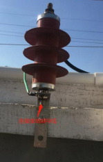
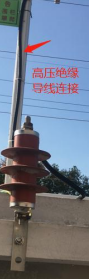
1.6.3 The steel wire at the top of the fence net is connected to the top terminal point of the lightning rod using high-voltage insulating wire.
1.6.4 From the bottom terminal of the lightning arrester, connect to the grounding rod using a standard grounding wire (usually a yellow-green copper wire). GroundingPiling should be driven into the ground.1.5 Mili Deep
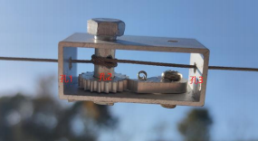
1.7 Installation of the Tension Engine
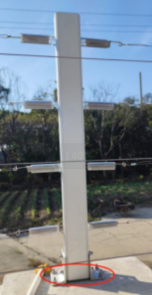
The Tension Host itself comes with a rainproof box, typically installed at the partition of the protective zone, on the wall below the tension control rod.1.7.1 The tension host is installed inside a waterproof box, and then the waterproof box is secured to the wall below the tension control rod with expansion screws.
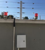
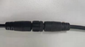
1.7.2 The five-core aviation connectors of the tension main unit are connected to the five-core aviation connectors of the tension control rod.
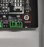
1.7.3 Grounding wires are drawn from the grounding terminal of the tension main, connected to the grounding stake. Note that this grounding stake must be spaced apart from the grounding stake of the fence.10 Please maintain a height of 2 meters or more to prevent backflow and damage to the equipment.
1.8 Installation of police lights
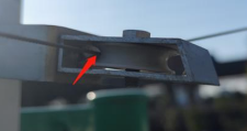
A warning light is installed in each defense zone, typically above the waterproof box where the tension main unit is located.1.8.1 The police lights are securely fastened to the matching bracket with their own nuts.
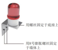
1.8.2 The police light with installed brackets will be...8 The expansion bolts were securely fastened to the wall.
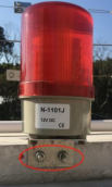
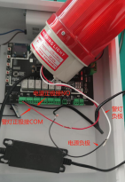
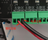
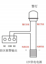
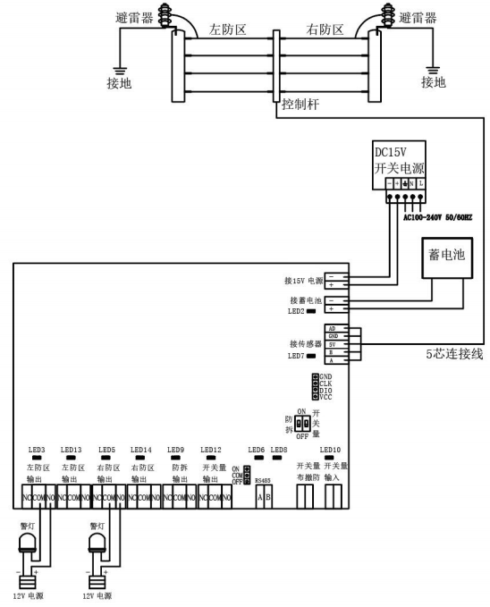
1.8.3 The police light has two wires (positive and negative poles), with a matching set.12V Our power supply (with positive and negative poles for the power cord, factory-fitted)Please provide the Chinese content to be translated.3.5mm Connect the negative terminal of the siren to the negative terminal of the power source, and the positive terminal of the siren to the positive terminal. (If necessary, consider trimming the connector.)Pulse Master Zone Alarm OutputCOM End, the positive terminal of the power supply is connected to the pulse host area alarm output.NO End.
Wiring DiagramWiring Diagram
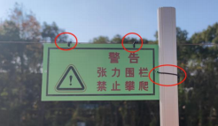
1.9 Installation of Warning Signs
Warning signs are installed on the stainless steel wire at the top of the fence, typically every10 Install a piece about 3 feet from the rod body.3 The Root Soft Metal Strip is secured with two holes fixed above on the top wireline, and the side holes are fixed on the rod body, preventing it from being blown away during strong winds.The warning sign kept swinging.
2.0 Power Cord Installation
Translate the tension host220V Plug in the power plug, installation complete.
Cabling Example
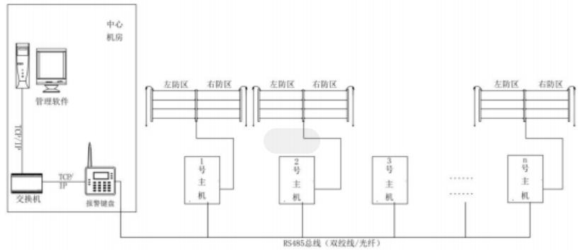
Tension Fencing4 Line system diagram
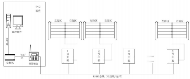
Tension Fencing6 Line System Diagram:
Tension Fencing Wiring Diagram
Tension Fencing Equipment Wiring Diagram
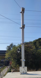
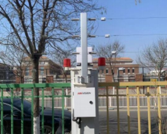
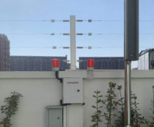
AppendixA Installation Example
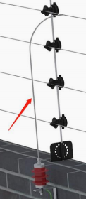
Metal fence side installation
Top of the fence installation
Minimal elevation differences installation
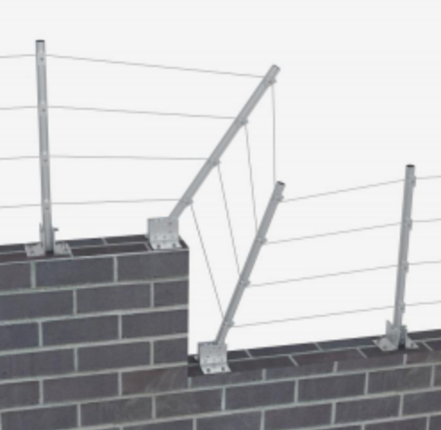
Installation with significant altitude differences