

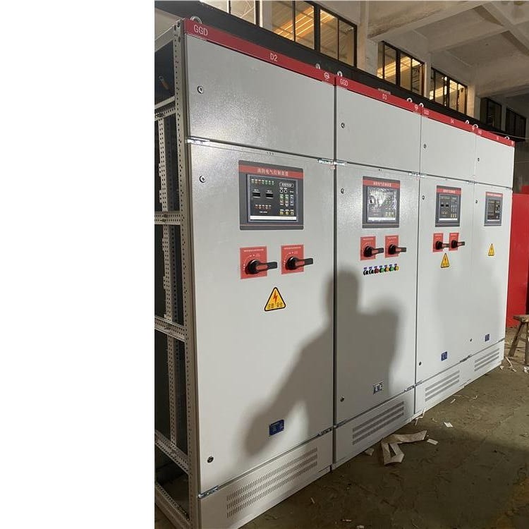
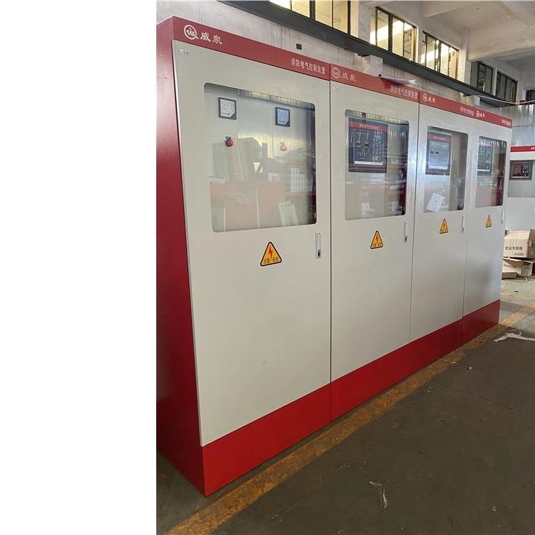
Water and fire have no mercy; these are things everyone knows. There are many fire hazards in life, but people often ignore the existence of these hazards. When a fire breaks out, people often feel helpless. In recent years, fire safety has been increasingly valued, and various fire protection equipment and systems have been established. A fire control cabinet is such a fire protection system. The fire control cabinet is located above the fire pump and represents the new generation of energy-saving water supply equipment. It is mainly used for water supply in high-rise buildings without towers and for constant pressure water supply by fire deep well pumps, among other scenarios, where the speed of the water pump needs to be adjusted in a closed-loop based on the real-time water usage conditions. It utilizes a variable-frequency drive, intelligent controller, pressure sensor, and pump to form a closed-loop control system. The multi-pump control ensures stable pipeline pressure, improves water supply quality, reduces secondary pollution, and boasts high energy-saving efficiency, enabling an unattended automatic control system for water supply without towers. This control cabinet equipment is primarily used for scenarios such as water supply without towers in high-rise buildings and constant pressure water supply by fire deep well pumps, where the speed of the water pump needs to be adjusted in a closed-loop based on real-time water usage conditions.
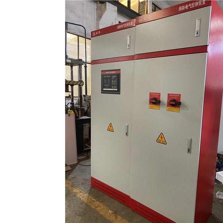
Adaptable to various harsh operating environments, with strong anti-interference and reliability, far exceeding other models.
Terminal block
This is definitely a must-have for every container, configurable based on the number of signals. If it's just a plain PLC control cabinet, these items are generally required. If your control cabinet needs additional components, adjust accordingly. For instance, if you need to power certain on-site instruments or small control boxes, you might need to increase the number of circuit breakers. Or, if you need to connect the PLC to a higher-level computer, you may have to add switches and the like.
Basic Structure of PLC Control Cabinet
A programmable logic controller is essentially a computer for industrial control, with hardware structure basically similar to that of a microcomputer, with the basic composition being:
1. Power Supply: The power supply of the programmable logic controller plays a crucial role in the entire system. Without a good, reliable power system, the controller would be unstable, hence the manufacturers of programmable logic controllers place great emphasis on the design and manufacturing of the power supply. Generally, AC voltage fluctuations within the range of +10% (+15%) can connect the PLC directly to the AC grid without any additional measures.
Unit 2: Central Processing Unit (CPU)
The Central Processing Unit (CPU) serves as the control center of the programmable logic controller. It receives and stores user programs and data entered from the programmer, as per the functions assigned by the programmable logic controller system program. It checks the status of power supply, memory, I/O, and warning timers, and can diagnose syntax errors in user programs. When the programmable logic controller is in operation, it first scans the status and data of various field input devices, storing them separately in the I/O image area. It then reads user programs one by one from the user program storage, interprets the commands, and executes logical or arithmetic operations as per the instructions, sending the results to the I/O image area or data registers. After all user programs have been executed, the output states in the I/O image area or data in the output registers are transmitted to the corresponding output devices, and this cycle continues until the operation is stopped. To further enhance the reliability of programmable logic controllers, in recent years, dual CPU redundant systems or triple CPU voting systems have been used for large programmable logic controllers. This ensures that even if one CPU fails, the entire system can still operate normally.
III. Memory
The storage device for system software is called the system program storage.
The storage for application software is called the User Program Storage. Four, Input/Output Interface Circuit
1. The field input interface circuit consists of an optocoupling circuit and a microcomputer's input interface circuit, serving as the input channel of the interface between the programmable logic controller and the field control interface.
2. The field output interface circuit is integrated by the output data register, strobe circuit, and interrupt request circuit. It allows the programmable logic controller to output corresponding control signals to the field execution components via the field output interface circuit.
