


During the user program execution phase, the programmable logic controller always scans the user program (ladder diagram) sequentially from top to bottom. When scanning each ladder diagram, it first scans the control circuit on the left side, composed of various switches, and performs logical operations on the control circuit in the order of left to right, top to bottom. Then, based on the results of the logical operations, it refreshes the state of the corresponding logical coil in the system RAM storage area; or refreshes the state of the corresponding output coil in the I/O image area; or determines whether to execute the function command specified by the ladder diagram. In other words, during the user program execution, only the states and data of input points within the I/O image area remain unchanged, while the states and data of other output points and soft devices in the I/O image area or system RAM storage area may change. The ladder diagram placed above affects those below that use these coils or data, while the ladder diagram placed below can only affect those above it during the next scan cycle. During program execution, if immediate I/O instructions are used, direct access to I/O points is possible. That is, even when using I/O instructions, the value of the input process image register is not updated; the program directly retrieves values from the I/O module, and the output process image register is immediately updated, which is different from immediate input.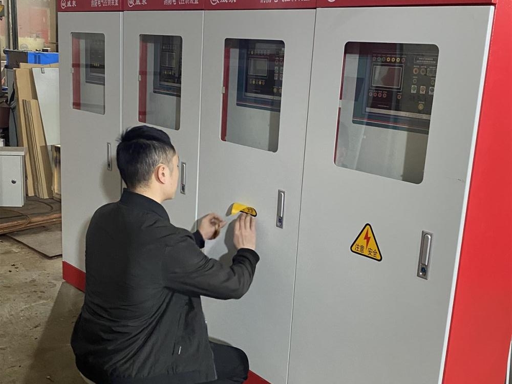
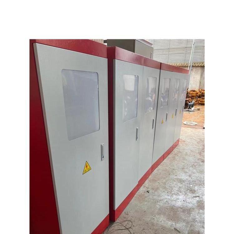
Electrical control cabinets, as the name implies, are cabinets used for electrical control purposes.
Electrical control cabinets feature traditional relays and PLC control. Simple controls are typically managed using relays, while complex controls usually employ PLCs. PLC stands for Programmable Logic Controller.
Electrical control cabinets are designed with varying control systems to meet different needs. They are assembled with different combinations of electrical components based on the number and size of the controlled devices. A simple electrical control cabinet for a single motor may include a circuit breaker, a contactor, a thermal protection element, a start button, a stop button, and two indicator lights.
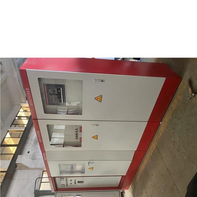
Fire Control Cabinet Functions and Features
1. The controller allows for adjustable set temperatures: the '+' key increases the temperature, while the '-' key decreases it. The controller displays the actual water temperature as the fire linkage control cabinet function.
2. Capable of using manual inspections for fire pumps, first, it cannot complete the low-frequency inspection process, which requires疏散 the site and conduct fire drills after each inspection, affecting work and life, and consuming manpower and resources. Second, the fixed water supply system for fire protection is an integrated system involving water and electrical circuits, both strong and weak currents, and the transmission, distribution, and control circuits. Manual inspections demand high personnel quality, making it difficult to ensure the quality and quantity of the inspection tasks. Third, full-time surveillance of the pump requires three standard working hours per day, conservatively estimating, a person's annual salary at 20,000 yuan, the annual labor cost would reach 60,000 yuan. Over ten years, the cost would amount to 600,000 yuan. The lifespan of the fire inspection cabinet is at least 30 years, with a one-time investment, high repetition, high reliability, and intelligent inspections will save the company a significant amount of manpower and resources.
3. Features low-speed pump inspection: The low-speed inspection does not add pressure to the pipeline system, eliminating concerns of pipeline and nozzle bursting.
4. Equipped with a patrol return signal from the main contactor. The feedback signal time allowance is not greater than 2S. After the main circuit patrol is completed, the patrol controller will issue the next patrol command to the pressure-free patrol device.
5. Features printout of fault parameters during inspection rounds.
Fire Control Cabinet Function and Features
1. The controller allows for adjustable set temperature: the '+' key increases the temperature, while the '-' key decreases it. The controller displays the actual water temperature as per the fire linkage control cabinet function.
2. The ability to use manual inspection for fire pumps includes the following: Firstly, it addresses the unachievable low-frequency inspection process, which requires疏散 (disperse) the site before conducting fire drills, impacting work and life, and consuming both human and material resources. Secondly, the fixed water supply system for fire protection is an integrated system involving water and electrical circuits, strong and weak currents, and power transmission and control circuits. Manual inspection demands high personnel quality, making it difficult to ensure the quality and quantity of the inspection tasks. Thirdly, full-time supervision of the pump requires three standard labor hours per day, conservatively estimating a salary of 20,000 RMB per person per year, leading to a human resource cost of 60,000 RMB annually. Over ten years, the cost would reach 600,000 RMB. With a fire inspection cabinet lifespan of at least 30 years, a one-time investment in high-repetitive, high-reliability, and intelligent inspection will save the company a significant amount of human and material resources.
3. Features low-speed pump inspection function: Low-speed inspection does not apply pressure to the pipeline system, eliminating concerns of pipeline and nozzle破裂.
4. Features a patrol return signal from the main contact of the contactor. The allowable feedback signal time is not greater than 2S. After the main circuit patrol is completed, the patrol controller will issue the next patrol instruction to the pressure-free patrol device.
5. Features fault parameter printing during patrol inspection.
Upon completion of the scanning user program in the output refresh phase, the programmable logic controller enters the output refresh phase. During this period, the CPU refreshes all output latches by accessing the corresponding states and data in the I/O image area, then drives the respective peripherals through the output circuit. This is when the actual output of the programmable logic controller occurs.
