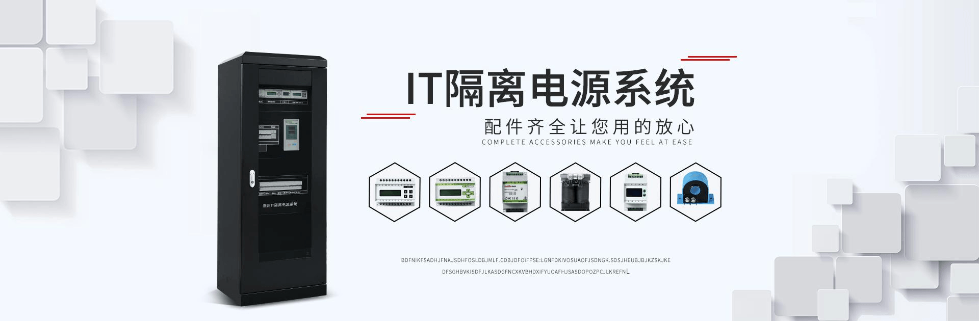
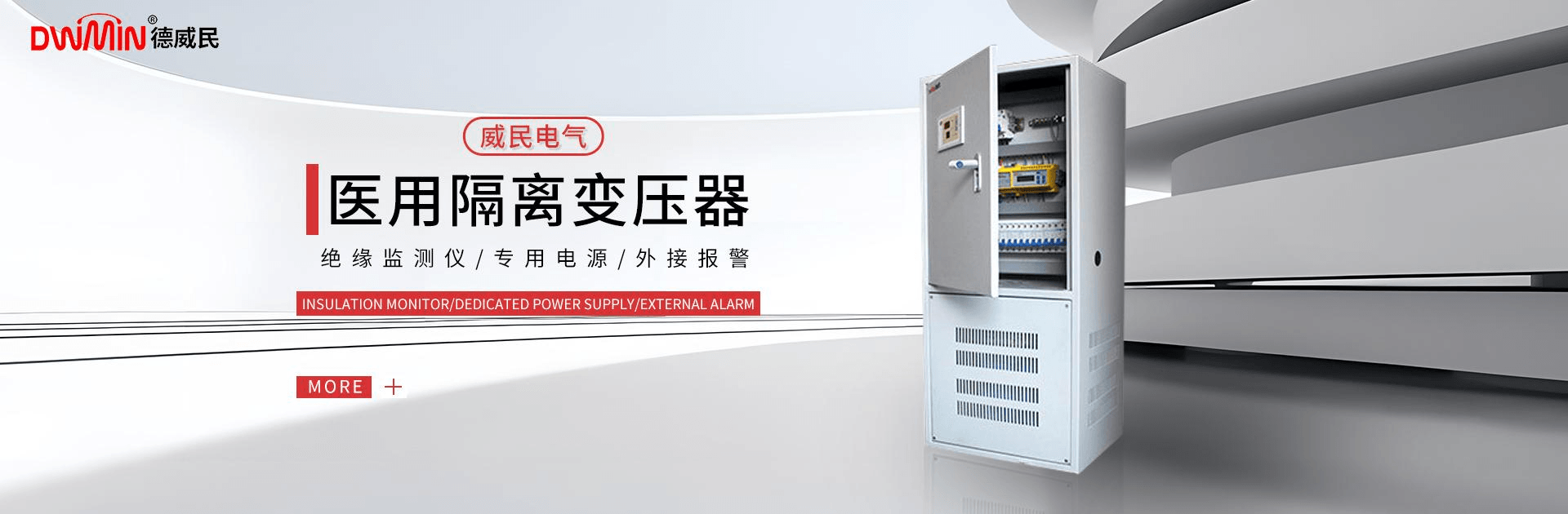
公司主营:Medical Isolation Transformers, Medical Transformers, Insulation Monitoring Instruments, Medical Isolation Power Supplies, Medical Transformers, etc.
13611889583
企业资质
Transformer Manufacturing Principles, Applications, and Parameter Analysis
2025-10-18
Transformers are devices that alter alternating current (AC) voltage, current, and impedance. When AC current flows through the primary winding, an alternating magnetic flux is generated in the iron (or magnetic) core, which induces voltage (or current) in the secondary winding. Transformers consist of an iron (or magnetic) core and windings, which have two or more coils. The coil connected to the power source is called the primary winding, while the remaining coils are referred to as secondary windings.
I. The Principle of Transformer Manufacturing:
In generators, whether the coil moves through a magnetic field or the magnetic field moves through a fixed coil, an electromotive force (EMF) is induced in the coil. In both cases, the value of the magnetic flux remains constant, but the amount of magnetic flux linking with the coil varies, which is the principle of mutual induction. A transformer is a device that utilizes electromagnetic mutual induction to transform voltage, current, and impedance.
Category
Categorized by cooling method: Air-cooled (self-cooled) transformers, Oil-immersed (self-cooled) transformers, Fluoride (evaporative cooling) transformers. Categorized by moisture protection method: Open-type transformers, Potting transformers, Sealed transformers.
Cores or Coil Structures: Core-type Transformers (Slotted Core, C-core, Ferrite Core), Shell-type Transformers (Slotted Core, C-core, Ferrite Core), Ring Transformers, Foil Transformers.
By Power Phase Classification: Single-phase Transformer, Three-phase Transformer, Multi-phase Transformer.
Power Transformers, Voltage Regulating Transformers, Audio Transformers, Intermediate Frequency Transformers, High Frequency Transformers, Pulse Transformers.
III. Characteristics and Parameters of Power Transformers
The core loss of a transformer at operating frequency is highly related to the frequency itself. Therefore, transformers should be designed and used based on the operating frequency, which is referred to as the working frequency.
Under specified frequency and voltage, the transformer can operate continuously without exceeding the rated output power that is within the permissible temperature rise.
Rated voltage refers to the voltage that can be applied to the transformer's coils, which must not exceed the specified value during operation.
The voltage ratio refers to the ratio of the primary voltage to the secondary voltage of a transformer, which is distinguished between no-load voltage ratio and loaded voltage ratio.
When the secondary winding of an unloaded transformer is open-circuited, there is still a certain amount of current in the primary winding, which is referred to as the no-load current. The no-load current consists of magnetizing current (which produces flux) and iron loss current (caused by core losses). For a 50Hz power transformer, the no-load current is essentially equal to the magnetizing current.
No-load loss refers to the power loss measured at the primary when the transformer's secondary is open-circuited. The main loss is core loss, followed by the loss generated by the no-load current on the copper resistance of the primary winding (copper loss), which is relatively small.
Efficiency is the percentage ratio of secondary power P2 to primary power P1. Generally, the larger the rated power of a transformer, the higher its efficiency.
Insulation resistance indicates the insulating performance between the various windings of a transformer, as well as between the windings and the core. The level of insulation resistance is related to the properties of the insulating material used, the temperature, and the degree of humidity.
Section 4: Technical Parameters of Low-Frequency Transformers
Technical requirements vary for different types of transformers, which can be expressed through corresponding technical parameters. For power transformers, key technical parameters include: rated power, rated voltage and voltage ratio, rated frequency, working temperature class, temperature rise, voltage regulation, insulation performance, and moisture resistance. General low-frequency transformers primarily have technical parameters such as: transformer ratio, frequency characteristics, non-linear distortion, magnetic shielding and electrostatic shielding, efficiency, etc.
Voltage Ratio: The two coils of the transformer have N1 and N2 turns, respectively, with N1 being the primary and N2 the secondary. When an AC voltage is applied to the primary coil, an induced electromotive force (EMF) is generated across the secondary coil. If N2 is greater than N1, the induced EMF is higher than the applied voltage, and such a transformer is called a step-up transformer. When N2 is less than N1 (n < 1), V1 is greater than V2, and the transformer is a step-down transformer. Conversely, it is a step-up transformer.
Transformer Efficiency: At rated power, the ratio of the transformer's output power to its input power is referred to as the transformer's efficiency, denoted as η for transformer efficiency; P1 for input power, and P2 for output power.
When the output power of the transformer, P2, equals the input power, P1, the efficiency, η, is 100%, and the transformer incurs no losses. However, such a transformer does not exist in reality. Whenever transformers transmit electrical energy, losses are inevitable, primarily consisting of copper losses and iron losses. Copper losses refer to the losses caused by the resistance of the transformer winding. When current passes through the winding resistance, some electrical energy is converted into heat energy and lost. Since the windings are typically made of insulated copper wire, these losses are termed copper losses.
Transformer iron losses encompass two aspects. First, hysteresis loss occurs when alternating current passes through the transformer. As the magnetic flux lines through the transformer's silicon steel sheets change in direction and magnitude, the molecules within the sheets rub against each other, releasing heat energy. This results in a portion of electrical energy being lost, which is known as hysteresis loss.
Another is eddy current loss, which occurs when transformers are in operation. Magnetic flux lines pass through the iron core, and on the plane perpendicular to the flux lines, an induced current is generated. Due to this current forming a closed loop and swirling like eddies, it is called eddy current. The presence of eddy currents causes the iron core to heat up and consume energy, and this loss is referred to as eddy current loss.
Transformer efficiency is closely related to the transformer's power rating. Generally, the higher the power rating, the smaller the loss to output power ratio, resulting in higher efficiency. Conversely, the lower the power rating, the lower the efficiency.
朱先生 (Mr.)
13611889583
13611889583
1460289013@qq.com
158 Hangye Road, Xiaoqunshan Town, Songjiang District, Shanghai, China, Building K14, Unit 2
b2b.china9.net © Zhongshang 114 Hebei Network Technology Co., Ltd.Address: Room 6009, Oriental New World Center, No.118 East Zhongshan Road, Qiaoxi District, Shijiazhuang City, Hebei ProvincePlatform Service Hotline: 4006299930
