

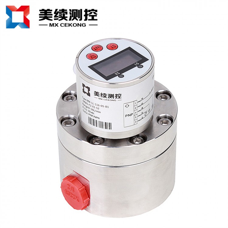
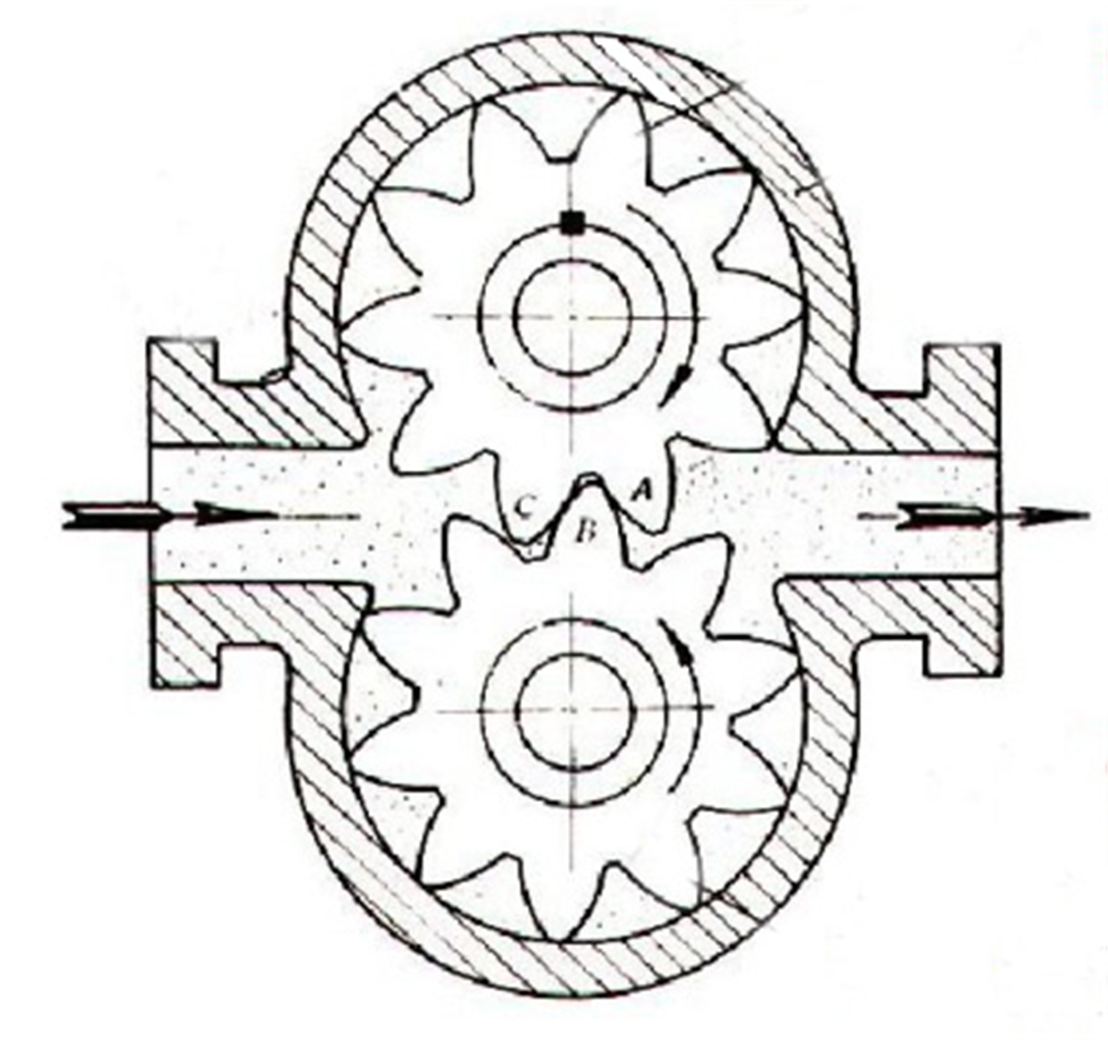
The Shanghai Meixu mx-ll-116-05 series gear flow transmitter is a volumetric flow transmitter. It is a transmitter for high-precision measurement of volume flow. As the medium flows, the gears mesh and rotate. Under the action of fluid flow, a pressure difference is formed at both ends of the instrument. It operates without power supply. A pair of gears rotate freely, and the cavity between the gears is filled with liquid. The liquid is discharged as it rotates, and the number of rotations of the gears can determine the flow rate of the liquid passing through the instrument.
The speed of the transmitter is detected by the sensor coil within the signal amplifier installed on the housing. The signal amplifier does not come into contact with the medium being measured. As the transmitter gears cut through the magnetic flux lines generated by the magnets within the housing, a change in magnetic flux occurs in the sensor coil. The sensor coil sends the detected magnetic flux cycle change signal to the pre-amplifier, where it is amplified and shaped to produce a pulse signal proportional to the flow rate. This signal is then sent to the unit conversion and flow accumulation circuit, where the cumulative flow value is obtained and displayed. Simultaneously, the pulse signal is also sent to the frequency-to-current conversion circuit, converting the pulse signal into an analog electrical current, which in turn indicates the instantaneous flow rate.
Unique Advantages
The cylindrical gear transmitter features high precision machining and precise installation. The gear rotation is non-contact scanned, with each tooth generating a pulse, resulting in an extremely high resolution. The cylindrical gear transmitter can measure very small flow rates and quantify small volumes of liquid.
Application Fields
Resin and Adhesive Measurement
Hydraulic Oil, Lubricating Oil, Grease Measurement
Water Treatment, Wastewater Treatment Plant (Environmental Pollution Control)
Slurries, sludges, pulp, and other fluids
Fuel oil measurement, ink, asphalt measurement
Chilled liquid, solvent measurement
Concentrating Equipment, Plant Extraction Equipment
Product Features
High-pressure resistant
Measurable for various adhesive media
High precision and high repeatability
Pulse output or analog output optional
Wide measurement range and wide range ratio
Excellent stain resistance
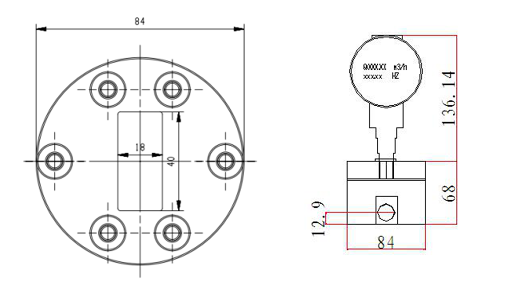
Standard Sizes
Parameter Specifications
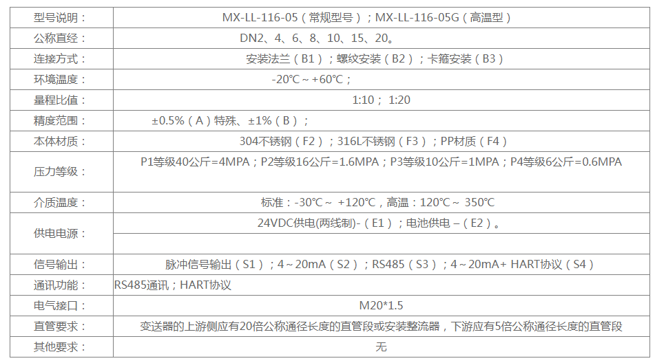
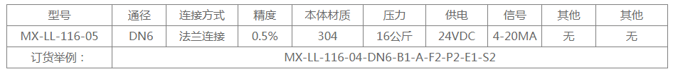
Selection Guide
Special Reminder
1. The installation location of the transmitter should be as far away as possible from environments with high temperatures, severe mechanical vibrations, strong magnetic interference, and high corrosiveness. The installation should be at a location that is easy to maintain and repair. The transmitter should generally be installed horizontally and must be securely fastened to the assembly with screws. If vertical installation is necessary, the liquid direction must be upwards. The pipeline should be filled with liquid completely, without any air bubbles.
2. The upstream side of the transmitter should have a straight pipe section of 20 times the nominal pipe diameter or an installed rectifier, and the downstream side should have a straight pipe section of 5 times the nominal pipe diameter.
Transmitters' types accessories should align with the pipeline centerline during installation, and the sealing gasket at the connection point must not extend into the liquid.
When installing a flow control valve is required, it must be installed on the downstream side of the sensor.
When installing sensors on new pipelines, it is recommended to install a filter upstream of the transmitter to prevent impurities in the pipeline from entering the transmitter.
To prevent disruption of the liquid's normal transmission during maintenance, a bypass piping system should be installed at the transmitter's location.
4. Magnetic fields and similar interference sources near the gear flow transmitter may affect the sensor's signal pickup. The connection between the transmitter and the display instrument should use a shielded cable with metal shielding, with the shield layer of the transmission cable grounded at a point on the display instrument end.
5. Header Wiring Method (Pulse Output): Three-wire wiring method: Brown: +11V-24V, Blue: GND, Black: IN
