


- AllProduct Category
-
Air-Cooled Modular Unit
Centrifugal Chiller Unit
Full-liquid Screw Chiller Unit
Water-Cooled Screw Chiller Unit
Water Source Heat Pump Unit
Cabinet Industrial Chiller Units
Tent Air Conditioners


详情描述
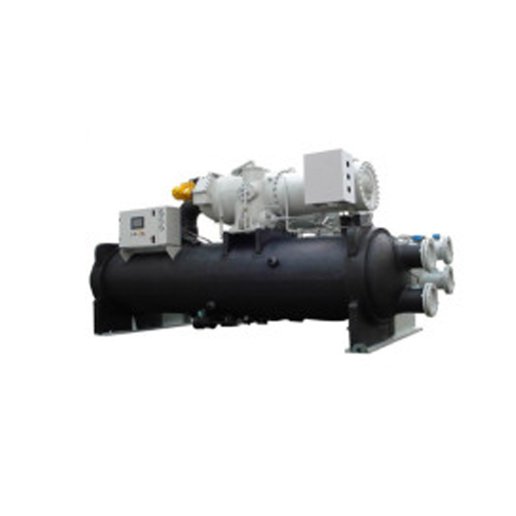
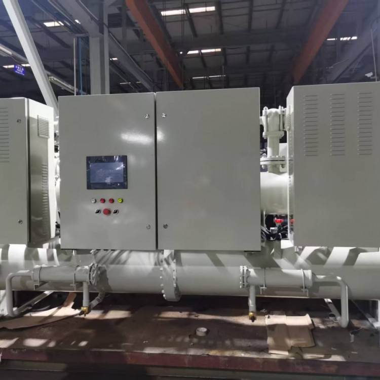
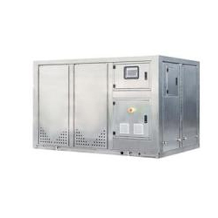
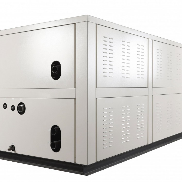
Centrifugal Water-Cooled Chiller Unit Overview
A. Features of Centrifugal Water-Cooled Chiller Units
1. Utilizing refrigerant, a HFC refrigerant, which is recognized internationally as an environmentally friendly refrigerant.
2. Positive pressure refrigerant; no need for exhaust equipment; simple room ventilation design.
3. Utilize Hanbell second-stage centrifugal compressor.
4. Utilize a falling film (spray tower) evaporator.
5. The unit features an integrated oil cooler, cooled by refrigerant, requiring no maintenance.
6. Utilizing a return oil system with * (suction pump return), ensures timely return oil under any load conditions.
7. The oil pump is integrated within the engine oil sump of the unit, ensuring no leakage concerns.
8. Utilizing a fixed orifice plate throttle device with no moving parts, it can promptly adjust the refrigerant flow under varying loads and operating conditions, without any lag, ensuring stable operation of the unit.
9. The microcomputer control system features a Chinese/English interface, clearly displaying all operational data, and is easy to operate.
B. High Reliability
1. Professional Design
With years of experience in the research, production, and sales of centrifugal water-cooled chillers, Hanbell, a centrifugal compressor manufacturer, has introduced the scientific research achievements from the Industrial Technology Research Institute and the U.S. specialized centrifugal machine consulting company NREC. The C series centrifugal compressors were officially launched at the Taipei Refrigeration Exhibition in 2007 and the Shanghai Refrigeration Exhibition in 2008.
2. Authorized Certification
Equipped with a large-scale online testing platform for centrifugal compressor units, this platform has been approved and evaluated as qualified by the National Quality Supervision and Inspection Center for Compressor Refrigeration Equipment (Hefei General Machinery Research Institute). The testing platform strictly adheres to national standards GB/T10870-2014, GB/T18430.1-2007, GB/T 19409-2013, etc. Each water-cooled centrifugal chiller is subjected to rigorous full-performance testing before shipment to ensure the performance of the units.
3. Reliable Return Oil Device - Jet Pump
The Comer centrifugal water-cooled chiller utilizes an ejector pump as the return oil component, powered by a medium-pressure flash gas, to complete the low-pressure side return oil function without any energy loss in the unit.
4. Refrigerant Flow Control Component - Orifice Plate
(1) Comer utilizes orifice plates as the refrigerant flow control device. Each set of orifice plates is custom-made according to the centrifugal compressor and unit performance, achieving an ideal match with the unit's specifications.
(2) Utilizing 2-3 orifice plates as a group of throttle devices, the first orifice plate acts as a liquid seal, while the 2-3rd orifice plates reduce pressure and throttle. This system relies on the dynamic balance of the refrigerant itself to ensure that the evaporator's required refrigerant flow can be instantly adjusted under full load, partial load, and various operating conditions.
(3) As the orifice plate has no moving parts, its reliability is naturally superior to that of various throttle valve assemblies with mechanical transmission during full load operation. With the liquid column height at H, the static pressure generated by the liquid column delivers the required refrigerant from the first orifice plate to the second one.
When the unit operates at half load, the liquid column height changes from H to H/4. Due to insufficient static pressure, the refrigerant passing through the first orifice plate is half of full load. The reduced upstream flow causes flashing between the two orifice plates, with a large amount of flashing gas mixed with liquid refrigerant passing through the second orifice plate, resulting in the refrigerant flow dropping to half.
C. High Efficiency and Energy Saving
Centrifugal Compressor
Centrifugal compressors feature two-stage compression, utilizing a main shaft made of high-strength alloy, an enclosed impeller of high-strength aluminum alloy, and precision gears with high precision. The bearings are equipped with high-strength ball/spherical roller bearings, non-flat type, ensuring resistance to emergency stops. The interval between startups can be shortened to 10 minutes, and the bearing lifespan reaches up to 80,000 hours.
2. High-efficiency Condenser
The condenser is divided into upper and lower sections with a flow guide plate in between, directing the liquid refrigerant to the shell edges. This significantly enhances the heat exchange efficiency of the lower copper tubes, making the design highly effective for large-tonnage units, reducing the condensation temperature by approximately 0.5℃ to 1℃.
3. Spray-type (Film-type) Evaporator
(1) The refrigerant entering the evaporator is sprayed downwards from the upper part of the heat exchanger tube array. The liquid refrigerant forms a thin film on the tube walls and moves downward, hence it is also known as a falling film evaporator. Due to the presence of only a thin layer of liquid refrigerant film on the surface of the heat exchange tubes, the heat transfer efficiency is excellent.
(2) The evaporator contains only a small amount of liquid refrigerant at the bottom, resulting in a lower refrigerant filling quantity for the unit, which meets environmental protection requirements.
(3) After a large amount of refrigerant evaporates, the lubricant concentrates at the bottom of the evaporator. The return pump can then smoothly extract the oil and return it to the compressor oil sump.
4. Economy heater, oil cooler, and return oil heat exchanger
(1) The integration of economizer, oil cooler, and return oil heat exchanger technology improves the separation of medium pressure saturated flash gas and medium pressure saturated liquid refrigerant within the economizer, resulting from system operation. The separated medium pressure saturated flash gas is then fed into the compressor for secondary compression.
(2) The rich oil liquid refrigerant from the evaporator is heated to refrigerant vapor and oil in the economizer, and then returns to the compressor oil tank.
(3) High-temperature refrigeration oil from the compressor first enters the economizer to cool to an appropriate oil temperature, and then is injected into the lubricated components of the compressor.
D. Advanced Control
1 Microcomputer Controller
Our centrifugal water-cooled chiller units are equipped with advanced microcomputer controllers, boasting computation speeds that can execute 1K Words programs in just 0.25ms, ensuring the unit's safe and stable operation.
2. Human-Machine Interface
The touch screen comes with built-in storage and offers a high response speed, allowing users to monitor the complete operating status of the water-cooled centrifugal chiller in real-time. The intuitive interface features English and Chinese language options, and operations and settings can be performed simply by clicking on the screen.
3. PID Control Function
The microcomputer controller utilizes advanced PID control functions to automatically adjust the unit's load based on the cold water outlet temperature and the target temperature. This ensures the water temperature reaches the required level within a short time and maintains stability within ±0.3℃ of the target temperature.
4. Engine Protection Function
The power supply for the centrifugal water-cooled chiller units to the client has been protected against overvoltage, undervoltage, three-phase imbalance, and phase reversal. The unit also features up to 30 protection functions.
5. Multi-functional anti-vibration protection
The water-cooled centrifugal chiller is equipped with advanced multi-surge prevention functions, combining prevention, control, and alarm methods to ensure the unit meets the customer's cooling capacity requirements within a safe operational range.
(1) Prevention - Through the calculation of the surge curve, the water-cooled centrifugal chiller automatically adjusts its state when the unit operation approaches the surge curve.
(2) Control - Adjust the operational status promptly when centrifugal water-cooled chillers exhibit surge, effectively controlling the occurrence of surge.
(3) Alert - If the engine surge persists for a certain period, an alert will be issued to notify the customer and initiate a shutdown action.
6. Reserved User Connection Points
(1) Provide cooling tower fan, cooling water pump, and chilled water pump control points for users, allowing the fans and pumps to be controlled by the unit, thereby optimizing the user's system structure.
(2) The centrifugal water-cooled chiller is equipped with reserved alarm output points for remote alarm display.
(3) Pre-allocated central monitoring connection points (Modbus-RTU communication protocol) for seamless integration with the building management system.


