


When customers encounter issues with their temperature and pressure reducing equipment, here's how to address them. We hope this helps solve problems for all our new and existing clients. Next, let's explore with the temperature and pressure reducer editor!
One: Analysis of the Causes of Pipe Hanger Suspension and Simplified Bend The temperature at the top of the pipeline section is higher than that at the bottom, which will result in axial bending deformation of the pipeline. This aligns with the theoretical analysis of actual pipeline deformation, indicating that the temperature difference between the top and bottom of the pipeline section is the main cause of the pipeline's bending deformation and the detachment of the supports and hangers.
Two, Analysis of Weld Crack Causes: The stress produced in pipes due to thermal expansion, contraction, and other displacements under constraint is referred to as secondary stress). The allowable stress value is 52.00 MPa [as specified in the Technical Regulations for Stress Calculation of Steam-Water Pipes in Thermal Power Plants (SDGJ6—90)]. The primary stress at the smaller end of the reducing tee is 35.71 MPa.
This highlights two key points:
① The intermediate support is suspended, resulting in excessive primary stress on the temperature and pressure reducing valve, which makes the pipeline behind the spray valve prone to cracking.
② The intermediate suspension brackets are suspended, and the primary stress at the smaller end of the transition piece is not significant (primary stress is within the acceptable range), and under the suspended condition of the brackets, the stress in the piping is not the main cause of cracking at that location.
The lower section of the throttle valve cross-section experiences thermal stress leading to weld cracks. There is a significant temperature difference between the upper and lower parts of the pipeline, especially during transitions to different operating conditions. When restarting, condensate may be present inside the pipe. High-temperature steam passing through the pipeline causes the dry pipe walls to heat up rapidly, while the water-retained sections heat up slower. This results in higher axial tensile stress at the lower temperatures, and this higher thermal stress or thermal fatigue is the primary cause of weld cracking.
Four: Countermeasures
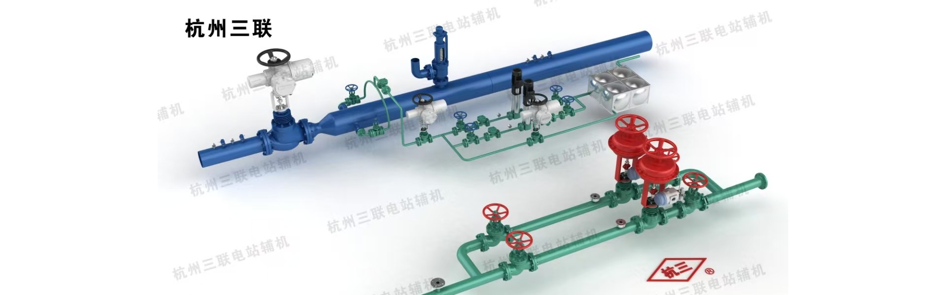
To address the issues of suspended sliding supports and bulging in the middle of the pipeline, the Xi'an Thermal Power Research Institute has redesigned the system's pipeline and selected the supports and hangers. This configuration allows the 6th and 8th supports to bear the load, while the 5th, 7th, and 9th sliding supports remain suspended. This solution resolves the issue of suspended supports and improves the structural stress of the temperature and pressure reducing valve.
(2) The addition of a hydrophobic pipeline has been implemented to enhance drainage conditions. Specifically, a 620mm drainage pipe has been added after the 6th support. This drainage pipe is activated during the warming-up and thermal standby of the temperature-reducing and pressure-reducing valve, thereby reducing the temperature difference between the upper and lower sections of the drum. This control of temperature difference across the pipeline cross-sections under various operating conditions minimizes pipe bending and eliminates weld seam cracks.
(3) Optimized the water spray device. The original spray position was at the 6# support bracket, and after the renovation, the water spray device is now placed at the pressure reducing valve. This arrangement ensures a more uniform mixing of the reduced water with steam, thereby reducing the temperature difference.

