


- AllProduct Category
-
Dust Collector, Vibration Absorber
Centrifugal Fan
High-Pressure Centrifugal Blower
Stainless Steel Fan
High-Temperature Fan
Air Conditioning Fan
Boiler Pass, Draft Fan
Dust Removal Centrifugal Fan
Coal Powder Centrifugal Fan
Fire Extinguishing and Smoke Exhaust Fan
Axial Flow Fan
Marine Fan
Material Conveyance Fan
Glass Line Blower
Electrical Fan Control


Recommended Products

详情描述
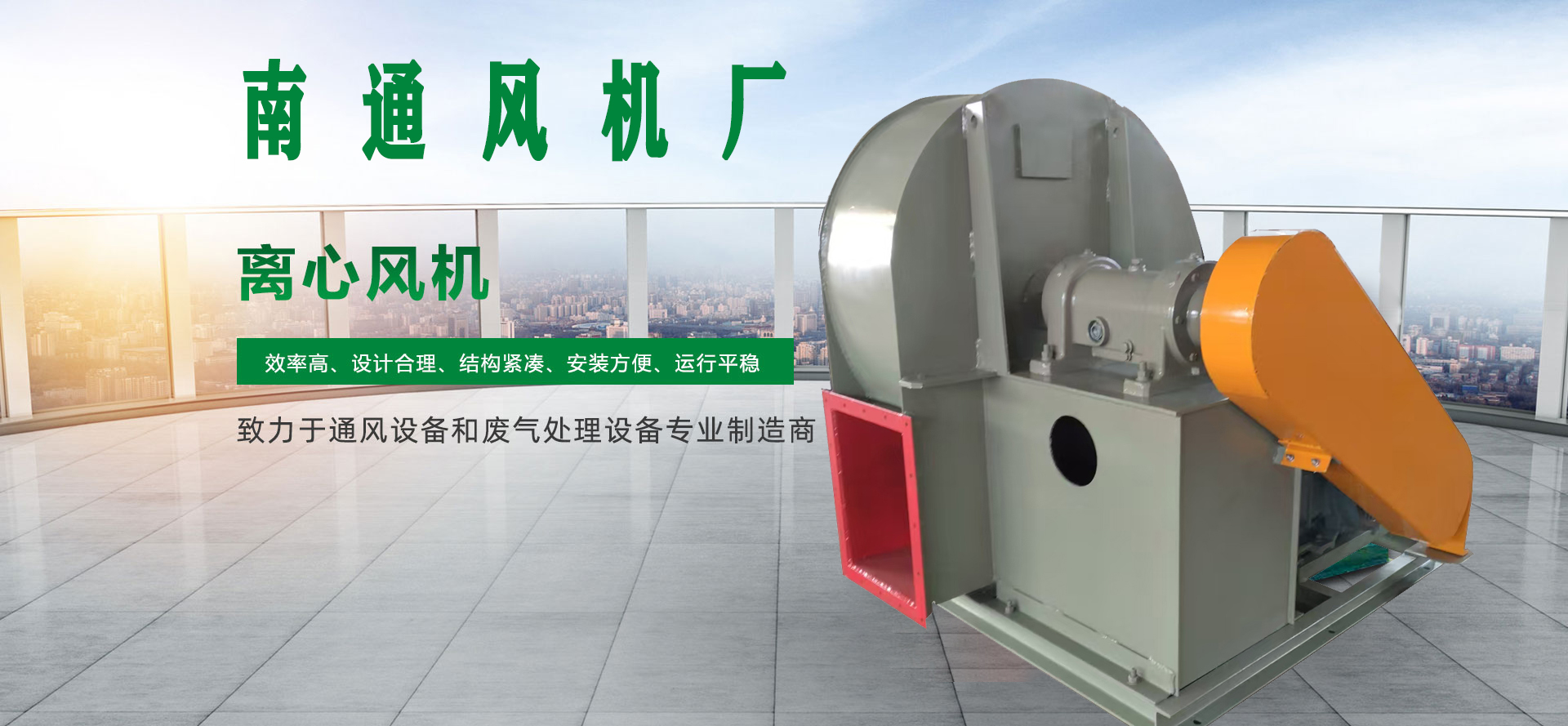
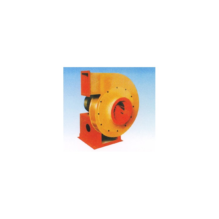
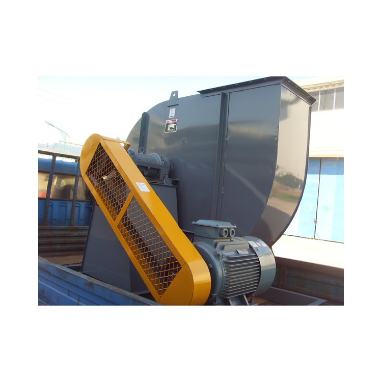
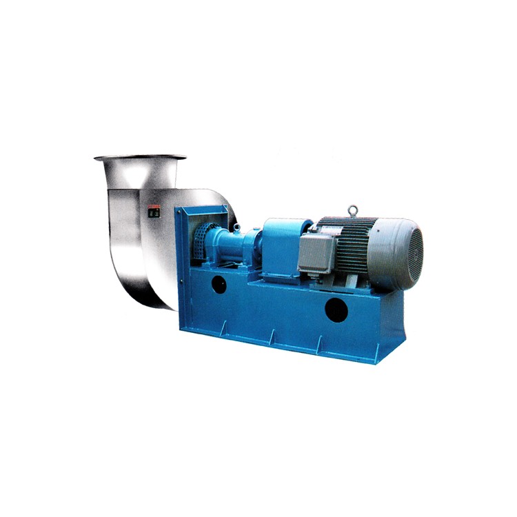
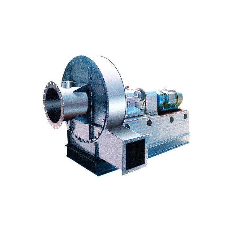
9-19(9-26)High-pressure centrifugal fan

Applications of 9-19 (9-26) High-Pressure Centrifugal Blowers: The 9-12 and 9-26 centrifugal blowers are generally used for forging and high-pressure forced ventilation. They are also widely used for conveying materials, air, and gases that are non-corrosive, non-self-igniting, and free of sticky substances. The medium temperature generally does not exceed 50℃ (not exceeding 80℃), and the dust and hard particles contained in the medium do not exceed 150mg/m3.
Section II: Type of Ventilator
This ventilator is a single-inlet type.NO4, 4.5, 5, 5.6, 6.3, 7.1, 8, 9, 10, 11.2, 12.5, 14, 16 – a total of 13 machine numbers.
Blowers can be manufactured in two types: right-handed and left-handed. When viewed from the positive end of the motor, if the impeller rotates clockwise, it is called a right-handed blower, indicated by "right"; if it rotates counterclockwise, it is called a left-handed blower, indicated by "left."
The outlet position of the fan is indicated by the outlet angle of the housing. "Left" and "right" can both be made in six angles: 0°, 45°, 90°, 135°, 180°, and 225°.
The transmission method of the fan isStyles A (NO4-6.3) and D (NO7.1-16).
Section 3: Structure of the Ventilator
NO4-6.3 is mainly composed of impellers, casings, inlet openings, brackets, etc.: NO7.1-16 is mainly composed of impellers, casings, inlet openings, transmission groups, etc.
Impeller:The 9-19 type fan blades consist of 12 pieces, while the 9-26 type fan blades are made up of 16 pieces. Both are of forward弯曲 blade design. The outer circumference speed of the impeller diffuser does not exceed 140m/S. The impeller is balanced both statically and dynamically after shaping, ensuring smooth operation.
Shell: Welded from ordinary steel plate into a helical shell as a whole.
Air Inlet: Constructed as a streamlined overall structure in a converging shape, fastened with bolts to the front cover assembly.
Transmission Group: Comprising the main shaft, bearing housing, couplings, etc., the main shaft is made of steel, the bearing housing features an integrated structure, utilizes rolling bearings, and is lubricated with bearing grease.
IV. Fan Performance and Selection
The 9-19 and 9-26 models are only provided with the dimensionless performance table and curves for the NO10 prototype. The dimensional performance of the fans above NO10 can be calculated using the given dimensionless performance table or curves.
By calculating the dimensional parameter formula from dimensionless parameters:
K—Motor Reserve Factor Formula:
When in an extremely standard condition, non-standard ηin — internal efficiency must be adjusted.
Performance in standard state after converting from the state in question, then based on the speed n —— revolutions per minute (r/min)
9-19NO10Dimensionless performance table of the sample
1 | 2 | 3 | 4 | 5 | 6 | 7 | |
φ | 0.03 | 0.037 | 0.044 | 0.051 | 0.058 | 0.065 | 0.072 |
ψ | 0.828 | 0.842 | 0.835 | 0.814 | 0.78 | 0.745 | 0.705 |
Ψd | 0.0478 | 0.0725 | 0.1025 | 0.1380 | 0.1793 | 0.2263 | 0.2792 |
λ | 0.03247 | 0.0389 | 0.0451 | 0.05125 | 0.05785 | 0.065 | 0.0725 |
ηin | 0.765 | 0.800 | 0.815 | 0.81 | 0.782 | 0.745 | 0.700 |
9-26NO10 Sample Unit's Dimensionless Performance Table
1 | 2 | 3 | 4 | 5 | 6 | 7 | |
φ | 0.08 | 0.09 | 0.1 | 0.11 | 0.12 | 0.13 | 0.14 |
ψ | 0.87 | 0.858 | 0.839 | 0.817 | 0.789 | 0.754 | 0.72 |
Ψd | 0.0745 | 0.0943 | 0.1167 | 0.1416 | 0.1692 | 0.1994 | 0.2323 |
λ | 0.0866 | 0.0951 | 0.1044 | 0.1143 | 0.1246 | 0.1343 | 0.144 |
ηin | 0.804 | 0.812 | 0.804 | 0.786 | 0.76 | 0.73 | 0.70 |
Electrical Machine Storage Prepared Thread Numbers
Output PowerKW | ≤0.5 | >0.5~1 | >1~2 | >2~5 | >5 |
k | 1.5 | 1.4 | 1.3 | 1.2 | 1.15 |
Fan performance generally refers to the ability to convey gas under standard conditionsStandard condition refers to atmospheric pressure Pa = 101300 Pa, atmospheric temperature t = 20°C, relative humidity 50%, air density ρ = 1.2 kg/m³.
Five Fan installation and operation
Prior to installation, all components of the fan should be inspected: Ensure that all parts are complete, that the rotation direction of the impeller matches the housing, and that all connections are secure. Check for any damage to major components such as the impeller, main shaft, etc., and verify the smoothness of the transmission group.
During installation: Pay attention to inspect the housing; there should be no fallen tools or debris inside. In some assemblies, to prevent rust and facilitate disassembly, apply a layer of lubricant or mechanical oil. When connecting the fan to the base and the air intake/exhaust pipes, adjust them to fit naturally without forceful connection. Do not allow the weight of the pipes to be placed on any part of the fan. Also, ensure the fan is level.
Installation Requirements:
(1) Install according to the dimensions and locations shown in the drawings. Ensure high efficiency by particularly ensuring the axial and radial clearance dimensions between the inlet and impeller.
(2) After installation, test the drive assembly and check for any signs of being too tight or collision with the fixed parts.
(3) The installation is complete, and the final inspection must pass before the fan can be tested for operation.
To prevent motor overload and damage, the fan must be started without any load (close the inlet valve, slightly open the outlet valve). If the condition is good, gradually open the valves until the specified operating conditions are reached. During operation, the current should be strictly controlled and should not exceed the rated value.
Operation of the fan:
(1) Prior to the fan's startup, the following preparatory steps should be taken:
Turn the inlet valve off and slightly open the outlet valve.
b. Check the gap dimensions of all parts of the fan, and ensure there are no collisions or friction between the rotating and fixed parts.
(2) After the fan starts and reaches normal speed, it should be frequently checked during operation to ensure the bearing temperature is normal. If there are no special requirements for the bearing temperature, the temperature rise should not exceed 40℃; the root mean square vibration speed at the bearing location must not exceed 6.3mm/s. In case of severe vibration, impact, or a rapid rise in bearing temperature, the fan must be stopped immediately.
Six Fan maintenance
1. Safety Precautions for Fan Maintenance:
Operation is permissible only when the fan equipment is completely normal.
② If the fan equipment is started after maintenance, pay attention to whether all parts of the fan are operating normally.
Regularly clean the internal dust and dirt from the fan, and prevent rust.
④ For the safety of personnel, maintenance of the fan must be conducted only when the unit is parked.
2. Important Points for the Normal Operation of Fans:
During the start-up, shutdown, or operation of the fan, if any abnormal phenomena are detected, they should be checked immediately. If it is a minor fault, the cause should be promptly identified and efforts made to eliminate it. For major faults, immediate shutdown and repair are required.
② In addition to replacing lubricants after each maintenance, lubricants should also be changed as needed under normal circumstances.
Seven Main Faults and Causes of Ventilators
1. Severe vibration of the fan
The fan shaft and motor shaft are not concentric, and the belt pulley slots are misaligned.
② Shell or inlet with impeller friction;
③ The basic rigidity is insufficient or not sturdy enough.
④ Blade wheel rivets loose or blade wheel deformation;
⑤ The impeller shaft bore does not fit the shaft properly, causing looseness.
⑥ Shell, bearing seat and bracket, connecting bolts loose between bearing seat and bearing cover, etc.
Inadequate installation of fan inlet and outlet ducts, causing resonance.
Leaf accumulation of dust and dirt, blade wear, impeller deformation, shaft bending causing imbalance in the rotor.
2. Excessive bearing temperature rise
Bearings housing severe vibration.
Lubricant is poor quality, has deteriorated, or contains impurities such as dust, sand, dirt, etc., or there is insufficient filling.
③ Excessive or insufficient tightness of bearing housing cover and saddle connecting bolts
④ Axle and roller bearing misalignment, front and rear bearings not concentric.
⑤ Roller bearing damage or bearing bending.
3. Excessive motor current or high temperature rise
① The intake and exhaust pipe gates were not closed while driving.
② Motor input voltage is low or single-phase power failure.
③ Affected by severe vibration of the bearing housing;
④ The spindle speed exceeds the rated value.
Section 8: Scope of Complete Sets for Single Machine Products
Fan1 unit, with matching motor 1 unit, foot bolts set 1 (NO4-6.3, 4 pieces, NO7.1 and above 8 pieces). Coupling set 1 (NO7.1-16).
Section 9: Order Instructions
Please specify the model number, speed, airflow, pressure, exhaust angle, rotation direction, and motor type and specifications when placing an order for the fan.
2. The impellers for the centrifugal fans 9-26NO8 (2900r/min) and NO16 (1450r/min) are made of alloy steel plate; negotiation with the manufacturer is required upon ordering.
询价单

