


- AllProduct Category
-
Diving Agitator
Company News
Dive Propeller
Industry News
Multi-Surface Blender
Paddle Mixer
Grille Cleaning Machine
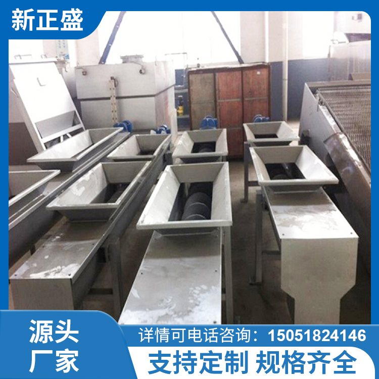
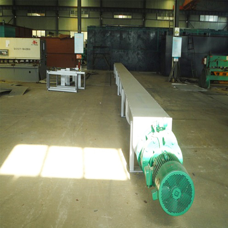
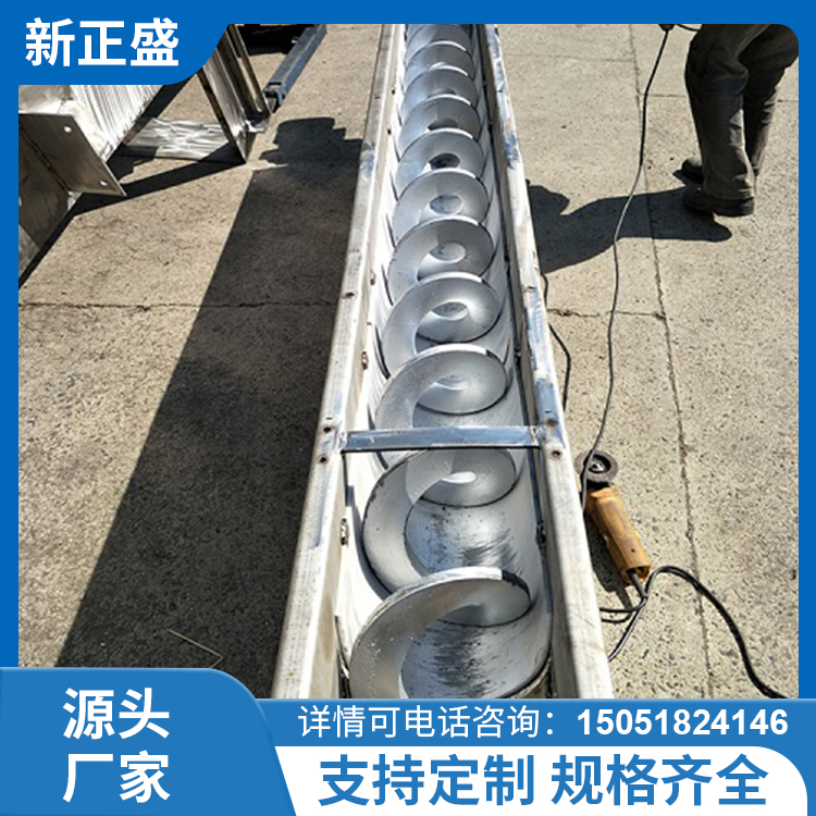
Spiral Conveyors
Diving, Buoy Aerator
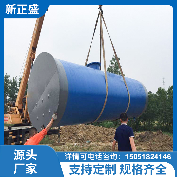
Integrated Rainwater Pumping Station


详情描述
One、Overview:
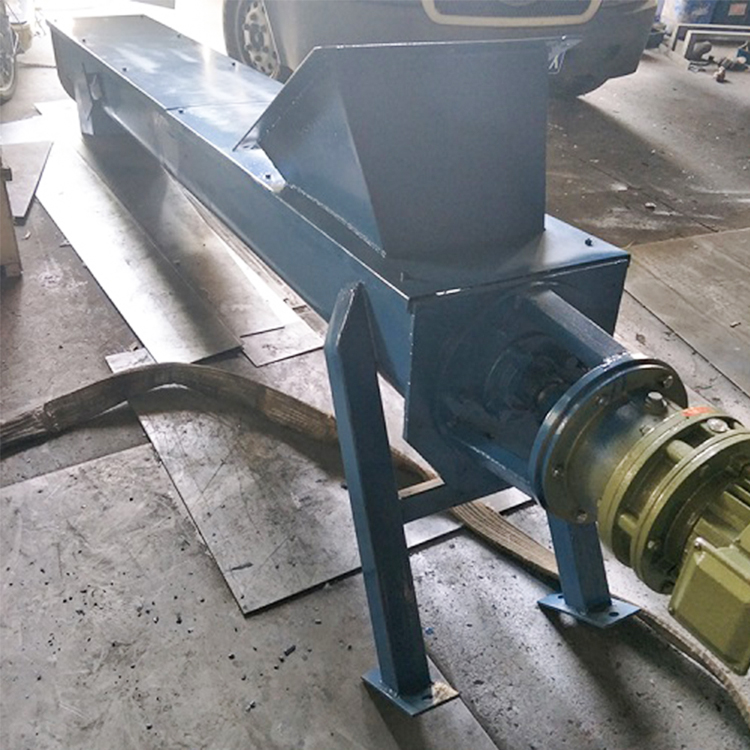
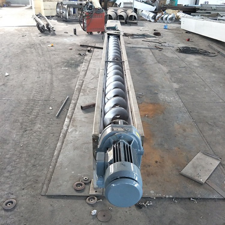
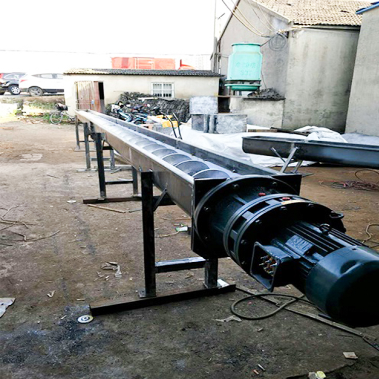
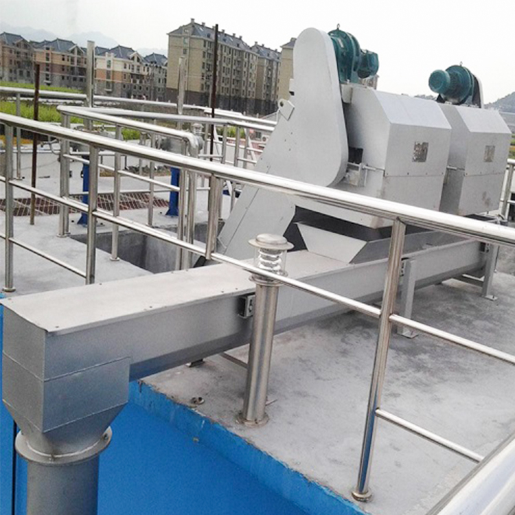
One of the commonly used continuous conveying equipment is the screw conveyor, due to its simple structure, small cross-sectional area dimensions, and especially its ability for enclosed conveying, which results in minimal environmental pollution. It is now being used in the wastewater treatment industry as one of the material conveying devices.
Section 2: Equipment Model Representation and Working Principle:
1. Method of Equipment Model Representation:
![]()
![]() WLS — 300
WLS — 300
![]() Spiral Diameter (Φmm)
Spiral Diameter (Φmm)
![]() Spiral Conveyor
Spiral Conveyor
2. Working Principle:
The material conveying of the screw conveyor is achieved by the sliding movement of rotating blades. The conveying direction determines the left or right rotation of the spiral blades and their rotational direction, allowing for either single-direction or double-direction conveying as needed, as well as multi-point loading. It can be installed horizontally or at a certain angle. Material enters the spiral from the feed opening (5) and is transported out through the discharge opening (1) or fed into an extruder or dehydrator after being pressed and dehydrated. The conveyor length L is selected by the user. The power drive unit (6) uses a double-curved gear reducer or worm gear helical bevel reducer. It can be installed at the inlet end (push-type spiral) or the outlet end (pull-type spiral). The U-shaped groove at the bottom of the equipment has a wear-resistant protective bushing, which is selected based on the type of conveying material.
3. Key Performance Indicators:
Spiral Diameter: Φ200-Φ400
Speed: 12 rpm - 20 rpm
Flow Rate: Q=2-6 cubic meters/hour
Feed Length: ≤15 meters
Installation Inclination: ≤ 30°
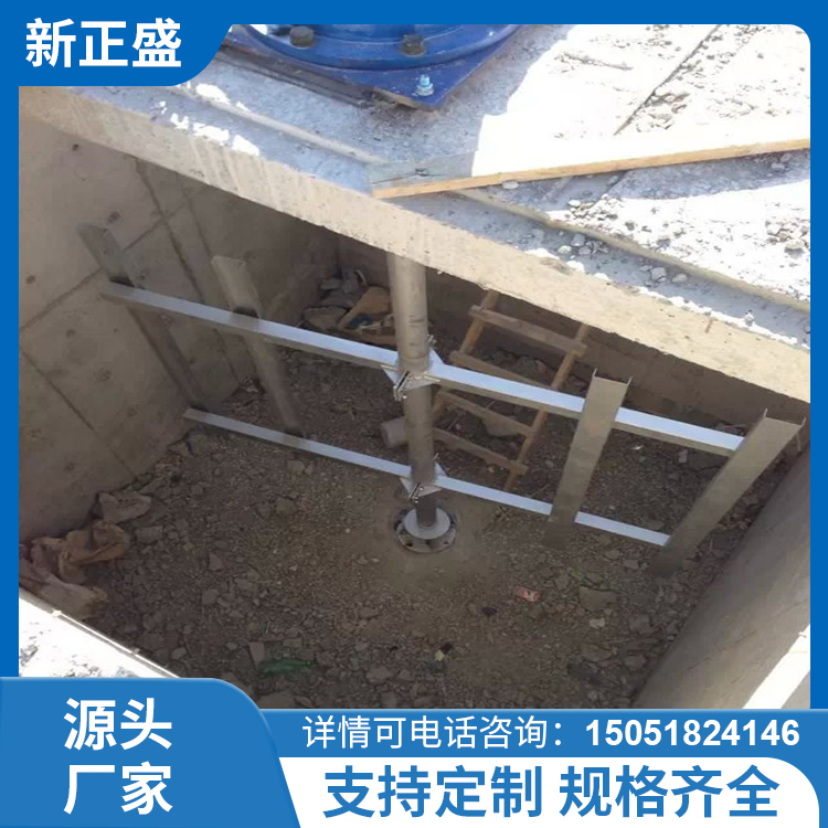
Section 3: Installation & Commissioning
If not specified in the order contract, the machine is factory-equipped with a ground stand based on the user's discharge height, secured during installation with expansion bolts.
2. Leave at least 0.7m of space above the top cover to ensure unhindered removal of the top cover, helix, sleeve, etc., during maintenance. Whether a drain is needed at the bottom of the equipment is determined by the customer at the time of ordering.
3. Horizontal conveyors installed horizontally have a horizontal tolerance of 1/1000 in length, while inclined installations have an angle error of ±1 degree.
4. Equipment must not collide or slip during hoisting, and effective measures must be taken to protect the stainless steel surface of the equipment. Scratches, wear, and dents are not permitted.
5. Before turning on, check if the helical pinion reducer oil level is normal. Change the lubricating oil after 300 hours of first use. For equipment running continuously for over 16 hours, replace the oil every 2500 hours. For equipment running 8 hours per shift, the interval can be extended to 4000 hours.
6. When conducting power-on testing, first perform a manual start to ensure there is no component friction before entering normal operation.
7. Run the machine for two hours to磨合 newly assembled parts, using some appropriate lubrication (such as).
Soy sauce solution is used to reduce vibration and noise, inspect for abnormal wear between the sleeve and the helix. Absolutely prohibited is the operation of the helix without material and lubrication measures, as it will severely damage the sleeve. (This applies to helices that do not have support at one end.)
Four: Usage and Maintenance
Operators must be trained and qualified before they can start operating.
2. Equipment is maintained in accordance with normal inspection, maintenance, repair, and lubrication management procedures.
3. Conduct daily inspections of machine operation, ensuring no abnormal noises, and add the appropriate amount of bearing grease. Check for leaks in the seals. Monthly, inspect the oil level in the drive unit gear box and top it up to the required level.
Open the top cover every six months to inspect the wear of the helix and sleeve, and check the tightness of all fastening connections.
Each year: inspect seal wear and replace as necessary.
Every two years: dismantle and overhaul the equipment, clean the bearing housing, replace worn parts, replace seals and worn bushings, inspect and correct the helix, etc.
4. The reducer speed and conveying capacity are selected according to customer requirements. The conveying material must be even and not excessive or oversized.
5. After a material blockage causes the spiral to shut down, the cause should be investigated and the fault resolved before restarting the machine.
6. When the machine is idle for three days or more, flush or remove internal materials to prevent drying and caking (especially when temperatures are high). In winter when temperatures are low, be cautious of freezing. Remove any caking or ice before starting the machine.
V. Equipment Spare Parts and Wear Parts List:
Serial Number | Part Name | Model Specifications | Material | Quantity | Note |
1 | Bearings | 1 set | |||
2 | Bearings | 1 set | |||
3 | Shell Oil Seal | Rubber | 1 piece | ||
4 | Oil Cup | M10×1 | 1 piece |
Section 6: Equipment Troubleshooting
Part | Fault Condition | Fault Cause | Exclusion Measures |
Driver Equipment | Motor fails to start | Fusible link fuse blown | Identify the cause and replace the fuse |
Thermal relay trips out | Identify the cause and resume | ||
Phase loss operation | Identify the cause and rectify the issue | ||
Motor steering opposite | Incorrect wiring phase sequence | Phase Transformation | |
Fuses blowing or thermal relays tripping | Electrical circuit short circuit | Repair wiring | |
Motor short circuit | Professional repair or replacement | ||
Motor overload | Identify the cause and reduce load operation. | ||
Motor overload | Main voltage exceeds technical parameters by 5% | Guarantee voltage is within the motor's technical parameter range | |
Excessive ambient temperature | Lower environmental temperature | ||
Motor blade is damaged | Repair and replace | ||
Material Clog Spiral | Clear clog | ||
Gearbox malfunction | Overhaul | ||
Gearbox failure | Internal parts wear and damage | Professionally repaired and installed | |
Safety pin break | Helical Blockage | Clear Material | |
Gearbox failure | Professional repair services | ||
Screw Spinning Body | Clog | Helical bend | Straighten or replace the helix |
Excessive materials | Remove excess material | ||
Frozen | Heating Melt | ||
Sleeve loose | Secure or replace bushes | ||
Material is extruded into the space between the feed trough and the liner. | Exclude | ||
Sleeve loose | Loose or missing connecting screws | Secure or replace screws | |
Material adhesion and accumulation between the feed trough and helix | Use the correct bushing | ||
Sleeve wear | Material transport alteration, does not comply with original design specifications. | Adjust or replace with other model bushes | |
Excessive idling time for equipment | Prevent | ||
Out Material Mouth | No shipment or Insufficient shipment quantity | Clog | Exclude |
Helical wear | Replace Spiral | ||
Excessive installation tilt of the equipment | Minimize the slope angle as much as possible. | ||
Material shortage | Adjust work shifts and single working hours |
询价单


