


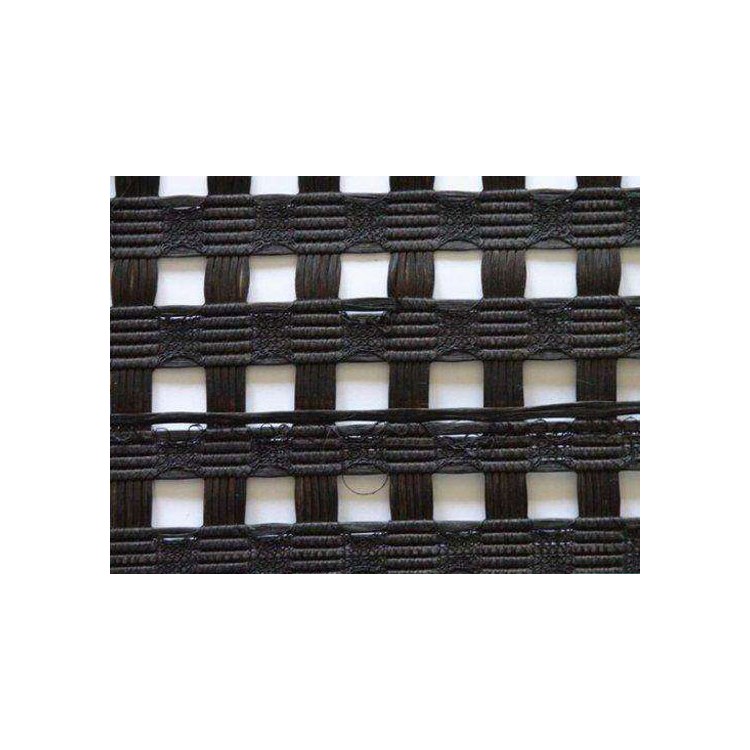
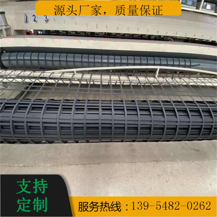
Steel-plastic geogrid
The Steel-Plastic Reinforced Geogrid is made by bonding steel-plastic reinforcing strips through a novel process. Due to its surface being pressed into a regular coarse pattern, it withstands high tensile stresses and friction with the backfill material when laid in the replacement soil layer, effectively limiting soil shear, lateral extrusion, and bulging. The high stiffness of the reinforced soil cushion layer facilitates the even distribution and transmission of upper foundation loads, spreading them over the underlying soft soil layer, thereby significantly enhancing the soil bearing capacity. The reinforced soil cushion layer, with its increased overall stiffness due to the geogrid, is beneficial for adjusting soil deformation. The flexible structural composite layer formed by using the steel-plastic reinforced geogrid can absorb seismic energy effectively, thus demonstrating excellent seismic performance.
I. Application:
Available for civil engineering projects such as highways, railways, embankments, bridge abutments, construction access roads, docks, revetments, flood defenses, dams, beachfront management, cargo yards, waste disposal sites, airports, sports fields, eco-friendly buildings, soft soil foundation reinforcement, retaining walls, slope protection, and road wear resistance.
II. Features:
1. High strength, low creep, adaptable to various soil environments, suitable for the use of tall retaining walls in high-grade highways.
2. Effectively enhances the interlocking and gripping action of reinforced load-bearing surfaces, significantly boosts the bearing capacity of the foundation, effectively restrains lateral displacement of soil mass, and strengthens the stability of the foundation.
3. Offers superior features such as higher strength, stronger load-bearing capacity, corrosion resistance, anti-aging properties, larger friction coefficient, uniform holes, ease of installation, and longer service life compared to traditional grates.
4. More suitable for deep-sea operations and embankment reinforcement, it fundamentally resolves the technical challenges of other materials used in stone baskets, such as low strength, poor corrosion resistance, and short service life due to long-term erosion by seawater.
5. Effectively prevents construction damage caused by machinery碾压 and destruction during the construction process.
Steel-plastic grill technical specifications application scope
Suitable for reinforced soil retaining walls, bridge abutments, slopes, and subgrade reinforcement, enhancing the bearing capacity of soft foundations and resisting the formation of soil failure surfaces.
Steel-plastic composite geogrids, due to their high tensile strength and low deformation, are widely used in soft soil treatment and the mitigation of uneven settlement of subgrades, particularly in the case of uneven settlement between new and old subgrades. Steel-plastic geogrids are more effective than plastic geogrids in this application. They are a material for dealing with uneven subgrade settlement. Reinforcement with steel-plastic composite geogrids in soft soil foundations promotes drainage with their mesh structure. Under embankment fill load, moisture in the soft soil is drained, facilitating soil consolidation and increasing the bearing capacity of the foundation. The combined action of soft soil foundation and steel-plastic composite geogrids forms an interlocking system. When subjected to vehicle loads, the vertical stresses on both sides increase, leading to a more uniform vertical stress distribution at the base.
Design Application
When geogrid is used for soft soil treatment, in addition to determining the placement and layers based on geological conditions, the design strength of the geogrid should also be determined according to the height of the subgrade fill.
When the backfill height exceeds 4 meters, the geogrid meets the low requirements of the industry standard, with the longitudinal and transverse ultimate tensile strength not less than 20 kN/m.
When the filling height is between 3-4 meters, the longitudinal and transverse ultimate tensile strength of the geogrid is not less than 40 kN/m.
When the fill height is less than 3 meters, the longitudinal and transverse ultimate tensile strength of the geogrid should not be less than 50 kN/m, and the elongation should be less than 4%. It is recommended to use GSZ60-60 type geogrid. When the geogrid is used at the junction of subgrade filling and excavation, a geogrid with a bidirectional tensile strength not less than 40 kN/m should be used, and GSZ60-60 type geogrid is advisable.
When used for widening the junction of old and new roads, refer to the method of using grid panels as adopted in the expansion of the Shenyang-Dalian Expressway: For subgrades with an elevation greater than 3 meters, lay steel-plastic composite grid panels at a height of 20 cm from the top of the subgrade. The grid panels should have a longitudinal (perpendicular to the route direction) ultimate tensile strength of ≥60 kN/m and a transverse (parallel to the route direction) ultimate tensile strength of ≥20 kN/m, with an elongation of ≤4%.
Construction Method
1. The laying surface of the geogrid should be relatively flat. After the laying layer has passed the acceptance, to prevent longitudinal misalignment, first mark white lines or hang strings along the width of the laying layer. Then, begin the laying process, and use U-shaped nails to secure the ends of the geogrid (use 4 nails per meter width, evenly spaced).
2. Secure the end of the grille, then pull it forward slowly using a laying machine or manually. Straighten it manually every 10 meters, and continue until a roll is completely laid out. Then lay the next roll, following the same procedure.
3. Laying out: Use the roll length as the unit for the length of the laying section. After the specified length for laying the grate is fully covered, perform a comprehensive check of the laying quality. Then proceed to lay the next section.
When laying the next section, the grids overlap by a grid spacing equal to the lap length, and they are secured with binding wire before continuing to lay the second section forward. Proceed similarly; the operation requirements are the same as before.

