


The working pressure and flow rate of the unloading crane pipe do not have a unified fixed value; the core is customized according to the conveying medium, structural type, and operational requirements. The industry has clear conventional design ranges, and the flow rate is significantly affected by pipe diameter, medium viscosity, and unloading method (gravity/pump pressure). Below is the general industry standard range plus precise parameters for different conditions, for reference in selection, design, and operation:
Core Work Pressure Range (General Design Value, Applicable to Over 90% of Operating Conditions)
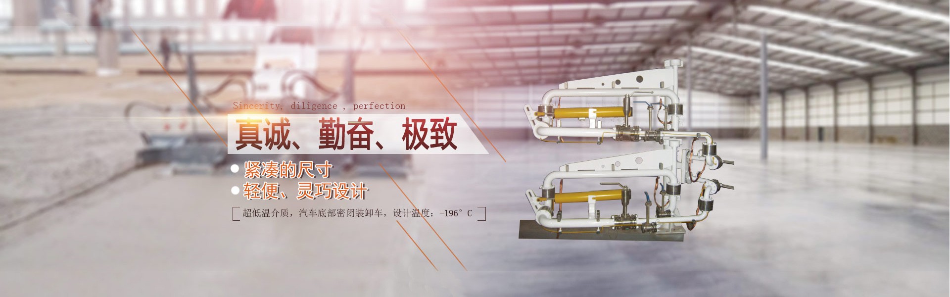
The unloading crane pipe is designed for the handling of atmospheric/low-pressure fluid, without high-pressure conditions. The design pressure is significantly higher than the actual working pressure, ensuring operational safety. It is available in standard and special chemical models.
Standard Oil and Chemical Products: Designed working pressure of 0.6MPa (6bar), actual working pressure ≤ 0.4MPa, compatible with gasoline, diesel, general solvents, and the majority of other media.
High-pressure Chemical Special Model: Designed for unloading of liquefied gas and other pressure vessels, featuring a working pressure of 1.6MPa (16bar). This is a customized specification and requires matching high-pressure rotary connectors and sealing components.
Food Grade Model: Consistent with standard oil products, designed for working pressure of 0.6MPa, actual operation under atmospheric pressure (gravity flow), to prevent pressure damage to food-grade seals.
Note: All unloading crane pipes comply with the GB/T 14383 "Forged Steel Flanged Pipe Connections" pressure design specification and can be customized to high-pressure models up to ≤2.5MPa according to customer requirements.
Core Traffic Scope (Categorized by pipeline diameter / medium / loading and unloading methods, mainstream in the industry)
Flow rate is strongly correlated with nominal pipe diameter (with diameter being the core selection criterion), and the following order of preference applies: Submerged installation > Above-ground installation, Pump-assisted conveyance > Gravity flow, Low-viscosity medium > High-viscosity medium. Below is the conventional flow rate range corresponding to nominal pipe diameters (for light oil/low-viscosity chemical media, pump-assisted conveyance, industry-wide reference):
Nominal Pipe Diameter (DN), Standard Flow Range (m³/h), Compatible Applications
DN50 20-50 Small Unloading Area, Low-Flow Fine Unloading
DN80, 50-100 medium and small oil storage facilities/chemical industrial zones, mainstream models
DN100 100-180 Large Oil Storage Facilities / Petrochemical Industrial Parks, Best-selling Model
DN150, 180-300 oversized unloading area, bulk rapid unloading
III. Flow Correction for Different Operating Conditions (Key Influencing Factors)
Viscosity: For high viscosity media such as heavy oil and lubricants, an additional heating jacket is required, which will reduce the flow rate to 30% to 60% of the conventional value for the corresponding pipe diameter.
Loading and unloading method: Under the same pipe diameter, the flow rate of the bottom-loading type is 20% to 40% higher than that of the top-loading type (due to the absence of vertical pipe resistance in the bottom-loading type, with lower residual volume).
Flow Mode: Gravity-assisted flow accounts for 20% to 30% of pump pressure transmission (driven solely by the liquid level difference, without external force).
Pipe Resistance: When the crane arm is too long and there are too many bends, the flow rate will slightly decrease (resistance compensation has been made during design).
IV. Additional Key Design Parameters
Nominal Pipe Size: DN50~DN200 (Mainstream DN80/DN100)
Design Temperature: -40℃ to 120℃ (standard model); high-temperature models available for customization up to 200℃, and low-temperature models down to -60℃.
Sealing Pressure: Matches working pressure; static seal leakage rate ≤ 0.01 mL/min; dynamic seal (rotary joint) has no visible leakage.