


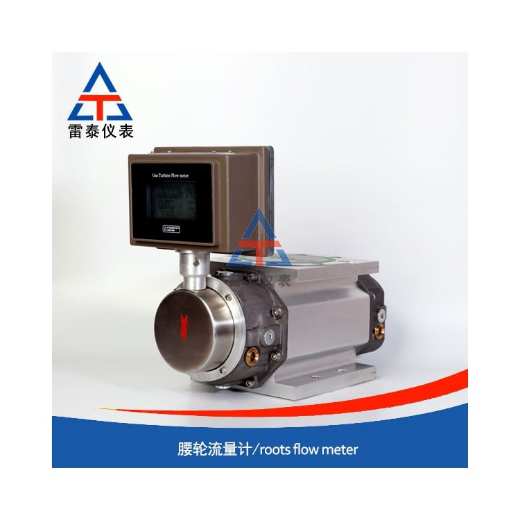
Product Overview: Waist Wheel Flow Meters
The waist wheel flow meter is mainly composed of three parts: the measuring chamber, a sealed coupling, and a counter. It can indicate cumulative and instantaneous flow rates on-site. With a transmitter and a flow intelligent control instrument, it can achieve remote measurement and control. It is widely used in the measurement of fluids such as petroleum and petroleum products, chemical solutions, etc., in various departments including oil machinery, chemical industry, power sector, metallurgy, transportation, food processing, and commercial trade.
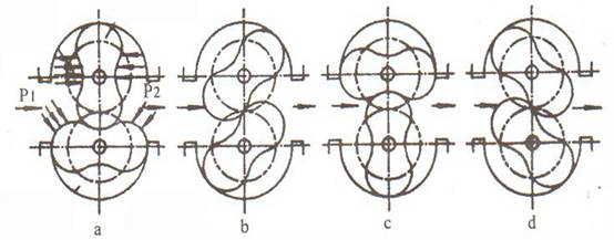
2. Working Principle
As the measured liquid flows through the measuring chamber, a pressure difference is formed at the inlet and outlet of the flowmeter, driving the turbine to rotate. Simultaneously, a pair of drive gears fixed on the turbine shaft ensures continuous rotation of the turbines. As the turbines rotate, the liquid is continuously discharged from the flowmeter through the measuring chamber. Each liquid volume passing through is four times the volume of the measuring chamber, and after the rotation count is reduced by a sealed coupling and a reduction mechanism, it is transmitted to the counter, indicating both the instantaneous and cumulative flow rates of the liquid. By installing a transmitter in the counter mechanism, the turbine flowmeter becomes a transmitter-equipped version. When paired with a display instrument or a microcomputer system, it enables remote transmission (quantitative, cumulative, and instantaneous functions) for automated measurement and control. Instructions for use are available in the display instrument classification manual.