


Product Details
Overview
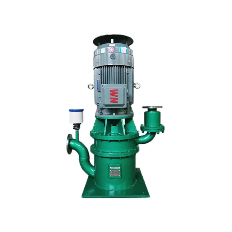
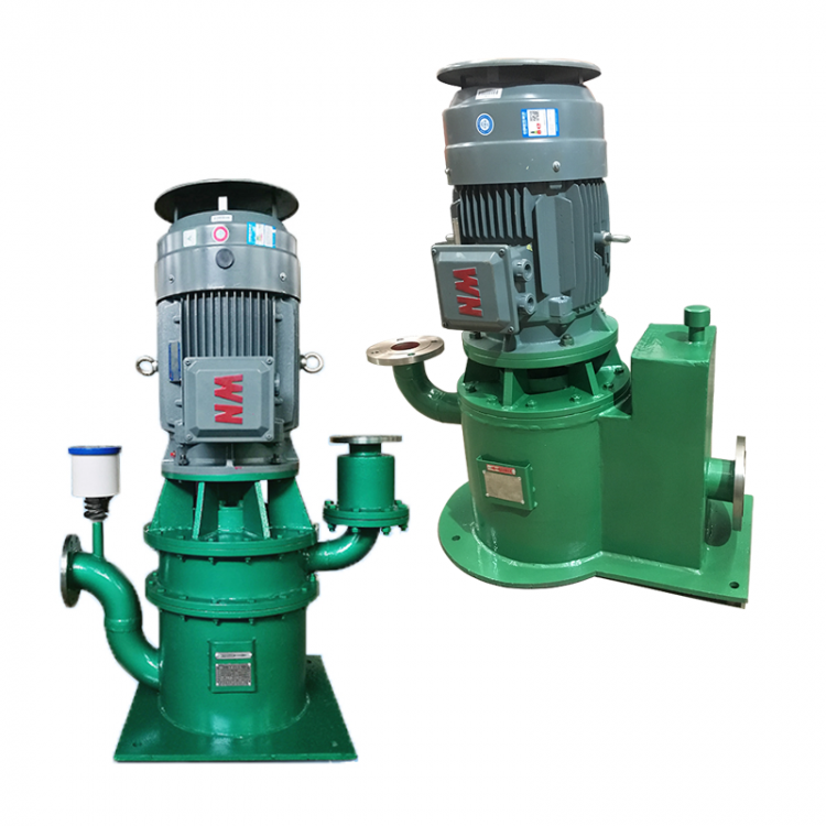
The WFB series sealed-free self-priming pumps feature multiple functions such as temperature and pressure resistance, "one-time drainage," and "lifelong self-priming." Currently, we produce a series of complete units in various materials including 321, 304, 316, 316L, A3, and PP (reinforced polypropylene), with five different designs and over a thousand specifications. These pumps are widely applicable in industries such as electronics, electricity, chemicals, metallurgy, food, electroplating, environmental protection, fire fighting, municipal, water purification, national defense military, textile dyeing, mining, and civil construction, and have received positive feedback from users.
Unique Advantages
1. Our company employs the "Chain-Type Multi-Face Centrifugal Seal Device for Pumps," which eliminates the traditional packing seal, gasket seal, and mechanical seal of water pumps, completely controlling "running, spilling, dripping, and leaking." It is an ideal equipment for replacing various long shaft submersible pumps, submersible pumps, and more.
2. The sealing device operates without friction, exhibits minimal wear, and boasts a longer service life compared to similar products.
3. Adopted the principle of vacuum pump transplant, featuring stable and reliable self-priming performance, especially with the use of "electronic air control valve," which truly achieves "one-time priming, lifelong self-priming."
4. Low vibration, minimal noise, flexible movement, easy to disassemble and install, no need for foundation bolts.
5. Features superior self-control functions, compatible with high-tech fields and highly automated systems.
Selection Methods
50WFB-AD1
50 - Pump Inlet Diameter (mm)
WFB - Non-sealed Automatic Self-priming Pump
AD1 - Performance Classification
The flanges of our water pumps are manufactured in accordance with the Chinese National Standard. Standard codes: GB9115.2-88; GB9115.3-88. The pressure rating for non-metallic material pump flanges is 0.6MPa; for metallic material pump flanges, it is 1.0MPa.
Please provide specific performance parameters, and we have professionals ready to assist and clarify any doubts, ensuring customer satisfaction.
Instructions for Using WFB Type Pumps
(1) Pump section
Once installed, fill the medium in the "drainage outlet" to the full for the "first drainage." No further drainage is required upon subsequent use. Tighten the "drainage outlet" and cap to prevent air leakage affecting the self-suction.
(2) Particle Size Specifications (Unit: mm)
Liquid intake diameter: Below 50, 50-100, 50-200, 200-300, 300-400, Above 400
Particle Diameter <3 <4 <4.5 <5 <6 <7
(3) It is mandatory to install the provided liquid intake bottom cushioning plate structure filter to prevent excessive particle absorption that could damage the pump and affect self-priming function.
(4) Water is prohibited for引流 during the transportation of concentrated sulfuric acid to prevent personal and equipment accidents.
(5) Prior to startup, ensure the pump shaft moves freely and check the rotation direction using a single-step method to confirm it aligns with the directional markings.
(6) Do not support the weight of the suction and discharge pipes on the flange of the pump discharge outlet; instead, they should be fixed on a support bracket (which the user must provide). All pipe connections must be tight and airtight; otherwise, it will affect the self-priming function and the flow head.
(7) When discharging a liquid containing crystalline or precipitated substances, if the pump is not used for a period of time, the pump cavity should be completely drained through the "vent port" to prevent crystalline or precipitated matter from remaining in the pump cavity, which could cause damage upon restart. Upon reusing, repeat the "drainage" process as outlined in item (1).
(8) For media without crystallization or sedimentation, such as after a long shutdown of the pump, before starting up, please check the引流液 (drainage fluid) at the "drainage port" to ensure it is sufficient. If not, please replenish it before attempting to self-siphon.
(9) During infusion, the flow rate, head (pressure), and suction stroke must be strictly controlled within the range specified by the selected model. Otherwise, it will cause excessive current fluctuations in the motor, affecting normal operation.
(10) When using in pools and containers below ground level, refer to the "Installation and Operation Diagrams" (Part One).
(11) If the pump is to be used in an environment with the pump submerged below the liquid surface, please refer to "Installation and Operation Diagram (II)."
(12) When supplying liquid to a high tank or water tower, please refer to the "Installation and Operation Diagram" (III).
(13) When handling media that produces bubbles, has high specific gravity, high lift, and a large static pressure in the discharge pipeline system, to accelerate the exhaust speed and shorten the self-priming time, please refer to the instructions in the "Installation and Operation Diagram" (IV) for Tip B procedure.
(14) When using the pool water in a fire suppression system, for the maximum reduction of water discharge time, please refer to the "Installation and Operation Diagram" (5).
(15) When using as a substitute for pipeline pumps and in closed-loop systems, refer to "Installation and Operation Diagram (Part Two)."
(16) "Drain ports," "overflow ports," "vent ports," "self-priming exhaust units," and "outdoor covers" are all unrelated to installation dimensions and system connections. The "self-priming exhaust unit" is only activated when there is a high vertical lift and a significant static pressure in the liquid pipeline system, and is generally not needed in standard process environments.
(17) This pump operates on the vacuum pump principle with self-priming. If designed for use in an "environment with specific requirements for discharge speed," the diameter of the pump's suction pipe should not be increased during installation, as this may affect the suction speed (except where there are no speed requirements).
(II) Electric Air Control Valve Section
(1) Non-professional electrical workers, do not open the guard to prevent electric shock accidents.
(2) Ensure the cable is securely connected to the pump motor terminals during installation after updating or repairing.
(3) Do not tamper with the sealing paint on the valve body. Please note the positioning marks before disassembly by the maintenance personnel for proper reassembly.
(4) The threaded connection for the pipe connected to the pump must be tightly sealed to prevent air leakage; otherwise, it will affect the self-priming function.
(5) Apply sewing machine lubricant inside the guide shaft and sleeve every six months; refer to the "Installation and Operation Diagram" (6).
(6) For the (11) and (15) environments of the "Pump Section," this valve is not recommended.
(3) Automatic Control Equipment Section
Customers with self-control devices for this machine will be provided with wiring diagrams separately, and please note the following:
(1) Non-professional electrical personnel should not open the screen door to prevent electric shock accidents.
(2) This unit is powered by a three-phase supply, voltage of 380V, and frequency of 50Hz. A circuit breaker protection must be installed in the incoming line circuit.
(3) Power Supply
