


Detailed Description
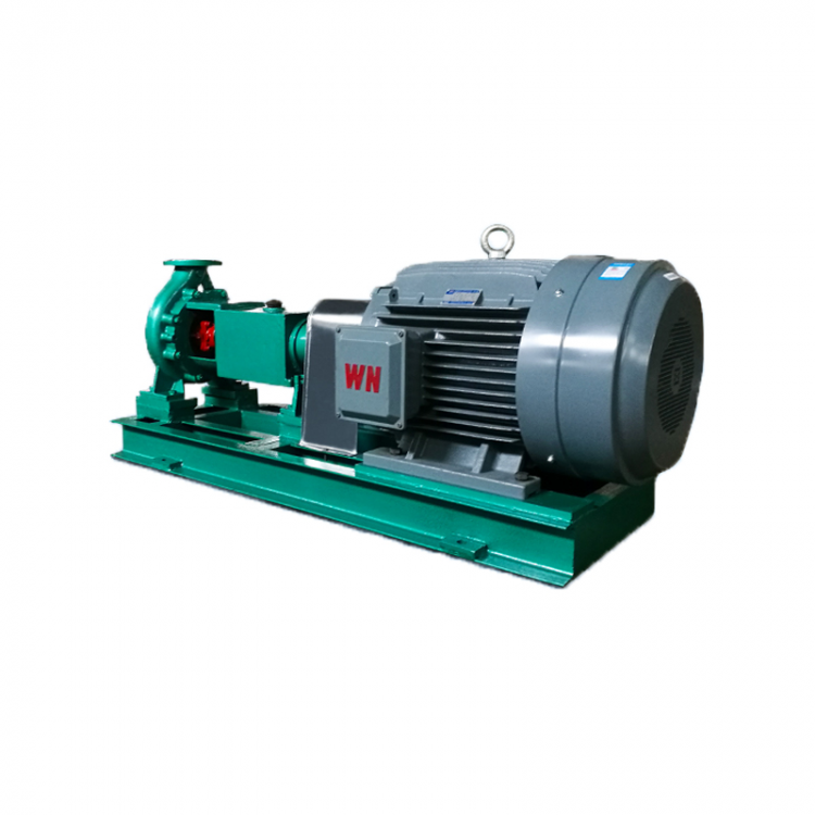
The HAF type chemical pump is a horizontal single-stage single-suction cantilever centrifugal pump, with its rated performance points and installation dimensions conforming to international standard ISO 2858. The manufacturing technical conditions comply with ISO 5199. This series of pumps is an improvement over the IH and HJ series pumps and is widely used in the chemical, papermaking, pulping, sugar refining, smelting, and textile and chemical fiber industries. It is particularly suitable for transporting low solid content slurry with suspended particles and crystalline mediums in chemical processes, wet metallurgical processes, and electrolytic circulation fluids.
II. Technical Specifications
A: First Cut Impeller Outer Diameter; B: Second Cut Impeller Outer Diameter

Section 3: Application Scope
Alkali Industry: Room temperature caustic soda for chlorine alkali production, chlorine products
Electrolytic copper-nickel electrolyte, acid fluid conveyance for producing drills, zinc, vanadium, gold, etc.
Steel Industry: Electroplating, Pickling
Acid Manufacturing Industry: Nitric acid, sulfuric acid, hydrochloric acid, phosphoric acid, malic acid, etc.
Petroleum & Chemicals: Production of refined acetaldehyde, alkylbenzene
Synthetic Fiber and Plastic Industry: Production, textile, dyeing and finishing of polyester
Pulp, cooking liquid, and bleaching liquid conveyance for the paper industry
Fertilizer Industry: Urea, Nitric Acid Production
Environmental Protection: Acid雾液的Transportation
Four: Performance
Flow Rate (Q): 6.3 ~ 400 m³/h
Flow Rate (H): 5~125m
Operating Temperature: -20°C ~ 180°C
V. Materials
Components in contact with the medium, the commonly used materials produced by our factory are as follows:
Corrosion-resistant alloy number | Applicable Medium |
304、316 | Room temperature, weak acidic |
825 | High-temperature dilute sulfuric acid |
HastelloyB | Hydrochloric Acid Jia |
HastelloyC | Hydrochloric acid of all concentrations |
C4 steel | Low-Temperature (Room Temperature) Concentrated Nitric Acid |
C6 steel | High-temperature concentrated nitric acid and mixed nitric acid with sulfuric acid |
329、CDtMCu | , Less than 40% of domesticftWarm dilute acid, low concentration mixed acid |
PureNiMonel | Alkali-resistant, sulfide alkali, caustic soda, chlorine gas |
H2 | Phosphoric acid and phosphoric ore slurry, stress corrosion resistance |
316L | Intergranular corrosion resistance |
HighCrGray Cast Iron | Corrosion-resistant |
ZSMAlloy Series | High-temperature wear-resistant and strong corrosion-resistant acid |
In addition to the materials listed in the table above, users are allowed to select other suitable materials required for the production of pumps in this series. The materials and their codes should, in principle, comply with the provisions of GB2100 standard. For materials for which the country has no specified codes, international or domestically recognized material codes (such as industry or company-specific regulations) may be used.
Section 6: Performance Table (I) for HAF Type Chemical Process Pumps
Model | Traffic<3 | Flow RateH | RPMn | PowerP(KW) | Efficiency | Permitted NPSH (Net Positive Suction Head) Allowance | HeavyM | ||
m3/h | L/s | m | r/min | Axial Power | Motor Power | % | m | ||
HAF50-125 | 5 | 0.19 | 0.55 | 45 | 2.0 | 107 | |||
HAF50-160 | 6.3 | 1.74 | 8 | 1450 | 0.34 | 0.55 | 40 | 2.0 | 119 |
HAF50-200 | 12.5 | 0.65 | 1.1 | 33 | 2.0 | 137 | |||
HAF50-250 | 20 | 1.27 | 2.2 | 27 | 2.0 | 182 | |||
HAF65 -125 | 5 | 0.31 | 0.55 | 55 | .2.0 | 125 | |||
HAF65 -160 | 8 | 0.53 | 0.75 | 51 | 2.0 | 128 | |||
HAF65 -200 | 12.5 | 3.47 | 12.5 | 1450 | 0.98 | 1.5 | 46 | 2.0 | 169 |
HAF65 -250 | 20 | 1.75 | 3 | 39 | 2.0 | 194 | |||
HAF65-315 | 32 | 3.3 | 5.5 | 33 | 2.0 | 260 | |||
HAF80-125 | 5 | 0.53 | 0.75 | 64 | 2.5 | 133 | |||
HAF80-160 | 8 | 0.88 | 1.5 | 62 | 2.3 | 179 | |||
HAF80-200 | 25 | 6.97 | 12.5 | 1450 | 1.49 | 2.2 | 57 | 2.0 | 199 |
HAF80-250 | 20 | 2.57 | 4 | 53 | 2.5 | 243 | |||
HAF80-315 | 32 | 5.07 | 7.5 | 43 | 2.5 | 323 | |||
HAF100-125 | 5 | 0.92 | 1.5 | 74 | 23.0 | 172 | |||
HAF100-160 | 8 | 1.58 | 2.2 | 69 | 3.4 | 192 | |||
HAF100-200 | 50 | 13.88 | 12.5 | 1450 | 2.5 | 4 | 68 | 2.5 | 245 |
HAF100-250 | 20 | 4.3 | 5.5 | 65 | 2.5 | 283 | |||
HAF100-315 | 32 | 7.5 | 11 | 58 | 2 | 344 | |||
HAF125-200 | 12.5 | 4.66 | 7.3 | 73 | 2.9 | 296 | |||
HAF125 -250 | 27.77 | 20 | 1450 | 7.56 | 11 | 72 | 2.3 | 288 | |
HAF125-315 | 100 | 32 | 12.82 | 18.5 | 68 | 2.5 | 490 | ||
HAF125 -400 | 50 | 22.69 | 30 | 60 | 2.5 | 640 | |||
HAF150 - 250 | 20 | 14.1 | 18.5 | 77 | 2.8 | 462 | |||
HAF150-315 | 200 | 55.55 | 32 | 1450 | 23.2 | 30 | 75 | 2.8 | 635 |
HAF150-400 | 50 | 38.9 | 55 | 70 | 2.5 | 837 | |||
HAF200 - 250 | 20 | 26.9 | 37 | 81 | 2.8 | 650 | |||
HAF200-315 | 400 | 111.1 | 32 | 1450 | 44.1 | 55 | 79 | 3.5 | 847 |
HAF200 -400 | 50 | 69.8 | 90 | 78 | 3.5 | 1140 | |||
HAF Model Chemical Process Pump Performance Table (Part Two)
Model | TrafficQ | Flow RateH | RPM (Revolutions Per Minute)n | PowerP(KW) | Efficiency | Allow NPSH Margin | Weight | ||
m3/h | 1/8 | m | r/min | Axial Power | Motor Power | % | m | ||
HAF50-125 | 20 | 1.33 | 2.2 | 51 | 2.0 | 135 | |||
HAF50-160 | 12.5 | 3.47 | 32 | 2900 | 2.37 | 4 | 46 | 2.0 | 167 |
HAF50-200 | 50 | 4.36 | 7.5 | 39 | 2.0 | 215 | |||
HAF50 - 250 | 80 | 8.25 | 15 | 33 | 2.0 | 293 | |||
HAF65-125 | 20 | 2.2 | 3 | 62 | 2.0 | 151 | |||
HAF65_ 160 | 32 | 3.82 | 5.5 | 57 | 2.0 | 194 | |||
HAF65 -200 | 25 | 6.94 | 50 | 2900 | 6.55 | 11 | 52 | 2.0 | 219 |
HA765 -250 | 80 | 11.84 | 18.5 | 46 | 2.0 | 366 | |||
HAF65-315 | 125 | 21.8 | 30 | 39 | 2.0 | 482 | |||
HAF80-125 | 20 | 3.95 | 5.5 | 69 | 3.0 | 199 | |||
HAF80-160 | 32 | 6.5 | 11 | 67 | 2.3 | 289 | |||
HAF80-200 | 50 | 13.88 | 50 | 2900 | 10.8 | 15 | 63 | 2.3 | 352 |
HAF80 - 250 | 80 | 19.11 | 30 | 57 | 2.5 | 510 | |||
HAF80-315 | 125 | 36.21 | 45 | 47 | 2.5 | 582 | |||
HAF100-125 | 20 | 7.07 | 11 | 77 | 4.2 | 282 | |||
HAF100-160 | 32 | 11.9 | 15 | 73 | 4.3 | 335 | |||
HAF100 - 200 | 100 | 27.77 | 50 | 2900 | 18.9 | 22 | 72 | 3.9 | 412 |
HAF100 - 250 | 80 | 32.28 | 37 | 68 | 3.6 | 525 | |||
HAF100-315 | 125 | 54.9 | 75 | 62 | 3.2 | 843 | |||
HAF125 -200 | 50 | 35.4 | 45 | 77 | 5 | 555 | |||
HAF125 -250 | 200 | 55.55 | 80 | 2900 | 58.1 | 75 | 75 | 4.5 | 845 |
HAF125-315 | 125 | 97.26 | 110 | 70 | 2.5 | 1318 | |||
Section 7: Structural Diagram
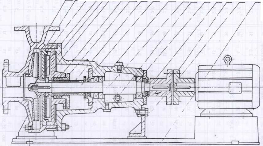
1. Pump Body 2. Impeller 3. Baffle 4. Power Impeller 5. Impeller Nut 6. Pump Cover 7. Packing Component
8. Filling Cover 9. Shaft Sleeve 10. Shaft 11. Bracket 12. Front Bearing 13. Oil Casing 14. Rear Bearing
15. Pump Coupling 16. Motor Coupling 17. Bracket 18. Base
Section 8: Brief Description of Pump Structure
1. The HAF series chemical pumps are mainly composed of
2. The HAF series pumps are equipped with power impellers and stop seals, ensuring no leakage over an extended period. The axial clearance of the power impeller cover does not exceed 0.8mm, which can be adjusted by a round nut. The stuffing box is fitted with a stop seal, containing two oil seals on the inside for sealing the liquid from the pump chamber. One oil seal is installed on the outside to seal the cooling water, which enters from below and exits above. The cooling water pressure should be slightly higher than the pressure at the inner diameter of the power impeller, approximately O.IMPa. When transporting fluids with a viscosity higher than 95cSt, to prevent vaporization of the medium at the power impeller, a water-cooled cover plate should be installed externally to cool the medium.
3. From the pump's suction inlet, the impeller rotates counterclockwise. A seal ring is fitted between the impeller and the drive impeller's end face, and a 0-ring is installed within the shaft sleeve to prevent leakage and corrosion of bearing components by the medium.
4. Double唇 skeleton rubber seals are used at the bearing cover and shaft bore, with an oil return channel below to effectively prevent lubricant leakage. Note that when installing the cover, the oil return channel should align with the oil return hole.
Section 9: Pump Installation and Usage
1. Assembly and Disassembly of Pumps
a. Disassembly sequence of the pump
Remove the oil drain plug from the pump bracket and drain the oil from the storage chamber.
Remove the bolts connecting the pump housing to the bracket, then extract all the rotor components including the bracket, sealing parts, etc., from the pump housing.
Loosen the hex nut at the rear of the shaft sleeve, unscrew the blade wheel flange nut, and remove the blade wheel and key.
Remove the partition and the impeller.
Loosen the connection screws between the pump cover and bracket, then remove the pump cover and shaft sleeve.
Remove the pump coupling and key.
7) Remove the bearing caps at both ends of the bracket, then pull the shaft and bearings out of the bracket together.
8) Disassemble the bearing and shaft.
b. Pump Assembly Procedure
The assembly sequence of the pump can generally be the reverse of the disassembly sequence, but attention must be paid to checking that all sealing surface gaskets are intact during assembly, and care should be taken not to miss any gaskets or replace any defective ones.
2. Pump Installation
a. After unpacking, inspect the pump and motor. If it is confirmed that there is no damage due to installation, unloading, transportation, or inspection, and that all fasteners are securely tightened, with the pump's inlet and outlet end caps intact and free of dust and debris, then there is no need for re-disassembly and assembly. Simply deliver it directly to the installation site for installation.
b. Level the base plane for pump installation using a level. After the cement base has cured, place the pump on the base and use a level to check the horizontal alignment of the pump and motor shaft. If not level, adjust with washers until level. Then, through the grouting hole, pour cement.
