

Overview
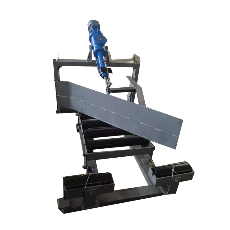
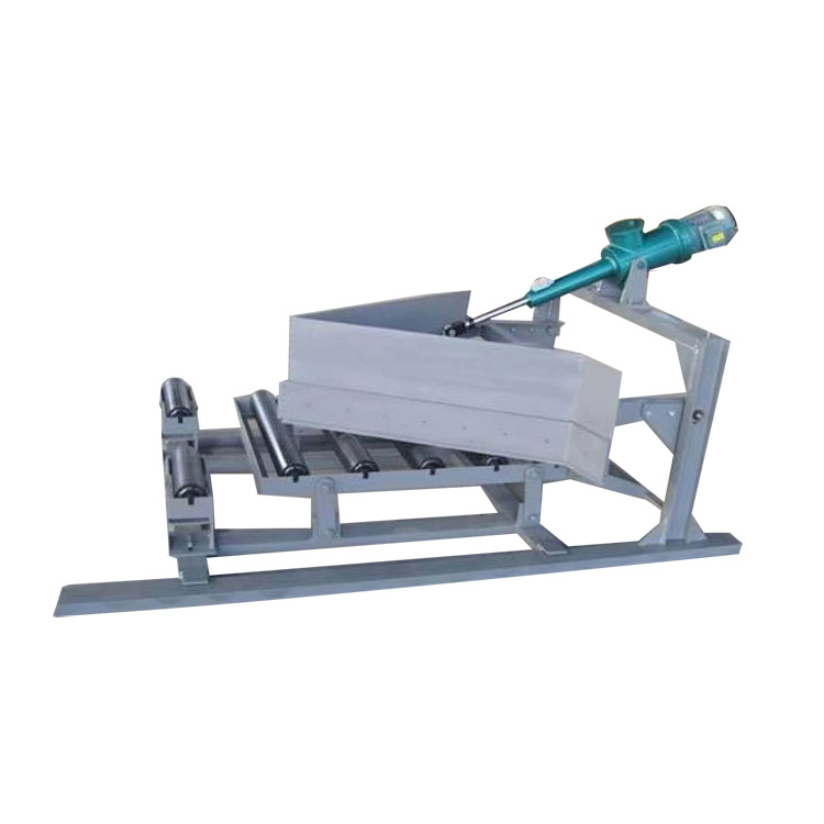
This product is widely used in mining, metallurgy, electric fields, coal transport stations, and port wharfs for the segmented unloading of conveyors. The hydraulic scraper unloading device is a mechanical product installed on the intermediate frame of a belt conveyor, responsible for unloading materials and controlling the flow and direction of material conveyance. It can evenly and continuously unload the material conveyed by the belt into a hopper or required location. This unloading device has been enhanced with variable slot angles, auxiliary scraper blades, and has been converted to an electro-hydraulic push rod power source, overcoming the shortcomings of the old-style unloading devices such as incomplete scraping of material, scraping the belt, poor overload capacity, and easy mechanical damage. The DYTN type single-sided and double-sided abrasion-resistant unloading device is powered by an electro-hydraulic push rod. During operation, the push rod extends to drive the driving rod, which moves the arm frame to lower the head and support the flat roller assembly, making the working surface of the belt flat, and the head lowers tightly against the belt surface, unloading the material from the belt into the hopper and transporting it to the required location. After unloading, the electro-hydraulic push rod retracts, pulling the driving rod back, raising the scraper head, and the variable roller assembly changes from flat to slot shape, allowing the material to pass smoothly (the principle of operation of the electro-hydraulic push rod is described in the push rod section).
Features
1. The power source drive section is the latest domestic two-in-one electric hydraulic push rod, featuring strong overload capacity, self-locking, and zero leakage. It achieves the lifting and lowering of the plow blade by controlling the motor's forward rotation.
2. The plow section is divided into the front part (alloy high-chromium manganese or asbestos material) plow blade and the rear part (wear-resistant rubber plate) plow head, for cleaner unloading.
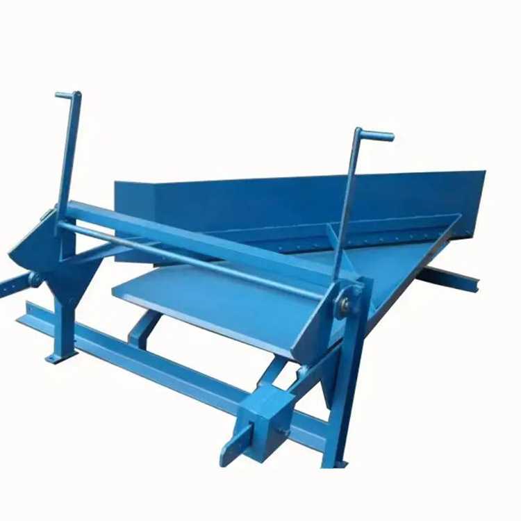
3. The added locking device on the plow head is a mechanical tension type, allowing for adjustable height of the plow blade to ensure a good surface contact with the belt. The plow blade will not lift or vibrate due to the impact force of coal during operation, thus preventing the belt from being torn, worn, or coal leakage. 4. The drive part's electro-hydraulic cylinder comes in two installation options: (1) the electro-hydraulic cylinder is placed above the coal separator, (2) or on the left or right side of the coal separator, for user convenience. 5. The discharge unit specifically uses a flip valve with a locking gas funnel made of high-chromium manganese material, (1) extending service life to 20 years and reducing maintenance; (2) reducing induced air draft to below 10% of the original; (3) ensuring uniform material flow, preventing spillage and sticking along the way.
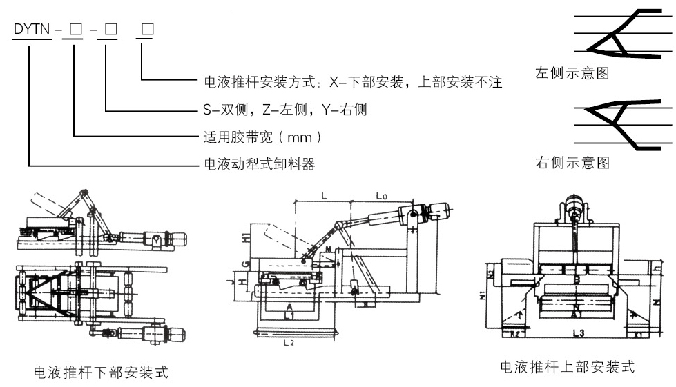
Product Model Coding Rules and Installation Diagram