


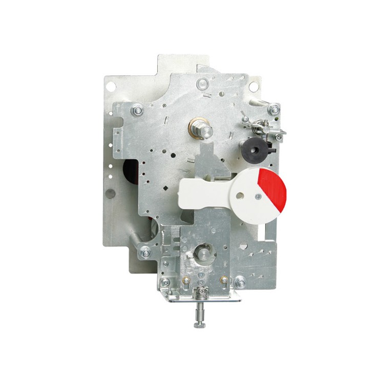


The KJF-06 series manual out-line operation mechanism is a matching equipment for the operation of switching on and off in the load switch of an inflatable high-voltage ring main unit. This series employs flat helical spring energy storage to control the switching action of the load switch, and uses compressed spring energy storage to control the switching action of the earthing switch. It features three operating positions: closing, opening, and grounding, and comes with a five-protection interlock function.
This series of products is fully inspected and certified before shipment, conforming to the following standards: GB 3804-2017 "AC Load Break Switches for 3.6kV-40.5kV", GB 3906-2020 ("AC Metal-Enclosed Switchgear and Control Gear for 3.6kV-40.5kV", "AC Load Break Switches and Fuse Combination Appliances"), and GB/T 11022-2020 "Common Technical Requirements for Standards of AC Equipment and Control Gear".
User Instructions
Closing operation:
First, check and confirm that the product is normal with no deformation. Then, install and secure the mechanism and load switch by aligning them through a three-position motion on the pressure box of the outgoing cable cabinet. Insert the hexagonal handle into the hexagonal shaft on the top, rotate it clockwise by approximately 90 degrees to store energy and automatically close the circuit, then remove the handle. This closure can only be performed when the grounding is disconnected and the operation is carried out correctly according to the signage. Otherwise, the plastic signage must be properly installed before operation, and the handle should not be forcibly inserted. When the load switch is in the closed position, the grounding operation port will be sealed by the closure/opening signage. At this time, the user must not violate the signage to forcibly operate grounding, as it will violate the five-protection operation requirements.
Circuit Breaker Operation:
Upon completion of the unit's closing operation, to open the circuit breaker, simply press the red button to disconnect the main circuit of the load switch. This disconnection can only be performed after the unit has been successfully closed; otherwise, it indicates an unsuccessful closure. After the disconnection, operations such as main switch closing or grounding closing can be carried out. This operation should not be performed by forcibly inserting the handle against the instructions on the signboard.
Grounding operation:
When the main switch is in the separated position, insert the handle into the six-sided pivot on the lower section and rotate it clockwise by approximately 90 degrees to close the grounding circuit, or counter-clockwise by approximately 90 degrees to open the grounding circuit. When the grounding is in the closed position, the operation hole of the load switch will be sealed by the switch position indicator. At this point, the user must not force the operation of the load switch against the indicator sign; otherwise, it will violate the five-prevention operation requirements.
Actuator dimensions and installation dimensions

