

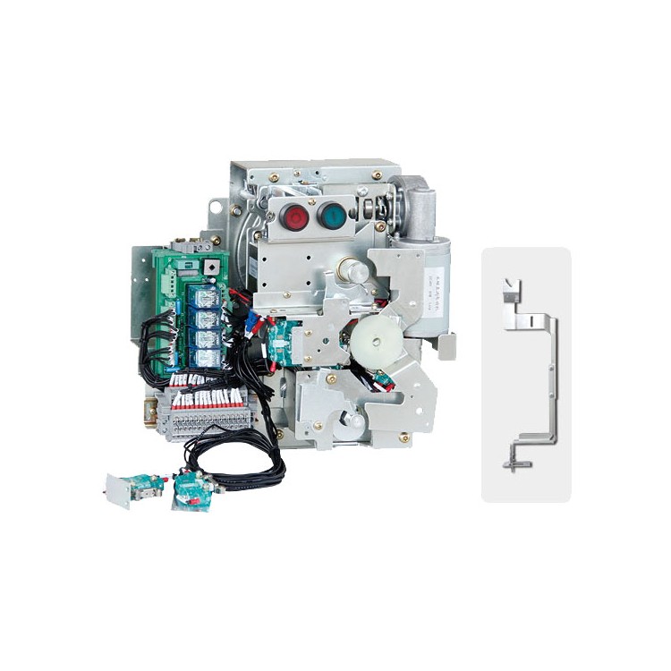


KJFD-02/MX Intelligent Electric Operation Solution, featuring an MCU chip integrated circuit for intelligent judgment of the closing/opening status of the load switch, performs electric operations on the mechanism according to customer instructions, enabling local closing/opening and remote closing/opening functions. It offers protection against motor overload, undercurrent, or jamming, ensuring the safety of critical components in the mechanism. The controller has a function to signal equipment faults, greatly facilitating daily maintenance.
KJFD-02/NX Standard Electric Operation Scheme, featuring PCB-type terminal integration, electric operation of the mechanism is achieved through relay contacts within the controller. It does not have motor protection or fault alert functions, categorizing it as an economical electric operation solution.
This series of products is factory-shipped after full inspection and meets the requirements of GB 3804-2004 "AC High-Voltage Load Break Switches for 3.6kV-40.5kV," GB 3906-2006 "AC Metal-Enclosed Switchgear and Control Equipment for 3.6kV-40.5kV," and "Combination of High-Voltage AC Load Break Switches and Fuses."
User Operation Instructions
Circuit Closing Operation:
Manual Closing: Secure the mechanism to the panel with the mounting bracket, then insert the handle into the operation shaft at the top of the mechanism and rotate it clockwise by approximately 90°. The mechanism's coiled double spring is compressed to store energy. Press the closing button to release the stored energy in the closing spring, and the main circuit of the load switch completes the closing operation under the power of the mechanism's release.
Electrical Closing: Upon power-up and the closing signal from the mechanism, the controller automatically identifies the on/off position of the load switch and the status of each interlock circuit. If all circuit statuses meet the closing conditions, the controller automatically energizes the closing solenoid, achieving an instantaneous closure of the main circuit of the load switch.
Operations: Disconnecting Switch
Manual disconnector: Press the disconnection button to release energy, and under the power of release, push the load switch to complete the main circuit disconnection action. For electric disconnection, a disconnection signal is provided; the controller will automatically determine the opening and closing position of the load switch and the status of each interlock circuit. If the status of all circuits meets the conditions for disconnection, the controller will activate the disconnection solenoid to release energy, achieving the main circuit disconnection of the load switch. The mechanism can perform main circuit closing or grounding closing operations when in the disconnection state.
Grounding, Closing, and Opening Contacts:
Grounding Closure: Insert the mechanism handle into the grounding operation shaft at the bottom of the mechanism, rotate clockwise approximately 90°. The grounding energy storage spring releases energy instantly upon compressing past the midpoint, pushing the grounding switch to complete the grounding closure. At this point, the mechanism interlock locks, preventing the main circuit closure.
Grounding Disconnector: Insert the mechanism handle into the grounding operation shaft at the bottom of the mechanism, rotate counterclockwise approximately 90°. As the grounding accumulator spring compresses past the midpoint, it releases energy instantaneously to push the grounding switch into the disconnected position. At this point, the mechanism interlock is engaged, allowing for operation of the load switch's closing and opening functions.
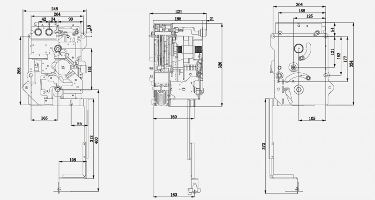
Actuator external and installation dimensions