


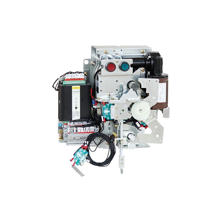
KJFD-01/MX Intelligent Electric Operation Solution, featuring an MCU chip integrated circuit for intelligent judgment of the closing/opening status of the load switch, it performs electric operations on the mechanism according to customer instructions, enabling local closing/opening and remote closing/opening functions. It also provides protection against motor overload, undercurrent, or jamming, ensuring the safety of critical components. The controller features a signal function for equipment fault alerts, greatly facilitating daily maintenance.
KJFD-01/NX Standard Electric Operation Plan, featuring PCB terminal integration and electric operation of mechanisms converted by relay contacts within the controller. It lacks motor protection and fault alert functions, classifying it as an economic electric operation solution.
This series of products is fully inspected and passes quality checks before being shipped, conforming to the requirements of GB 3804-2004 "AC High-Voltage Load Break Switches for 3.6KV-40.5KV," GB 3906-2006 "AC Metal-Enclosed Switchgear and Control Equipment for 3.6KV-40.5KV," and "High-Voltage AC Load Break Switch-Fuse Combination Apparatus."
User Instructions
Closing operation:
Manual Closing: Secure the mechanism to the panel by installing and fastening it. Insert the handle into the operation shaft located at the top of the mechanism, rotate the handle clockwise approximately 90°. The coiled double springs are compressed to store energy. Press the closing button, and the stored energy in the closing spring is released, completing the closing of the main circuit of the load switch under the mechanism's releasing power.
Electrical Closing: Upon receiving the closing signal from the power well of the mechanism, the controller automatically detects the on/off position of the load switch and the status of each interlocked circuit. If all circuit statuses meet the conditions for closing, the controller automatically activates the closing solenoid to energize, achieving an instantaneous closure of the main circuit of the load switch.
Circuit breaker operation:
Manual circuit breaker: Press the breaker button to release energy, and under the release power, push the load switch to complete the main circuit breaker action. For electric circuit breakers, a disconnection signal is sent, and the controller automatically identifies the position of the load switch and the status of each interlock circuit. If the circuit statuses meet the disconnection conditions, the controller automatically activates the disconnection solenoid to release energy, achieving the main circuit breaker disconnection. The mechanism can perform main circuit closing or grounding closing operations while in the disconnection state.
Grounding, closing, and opening contacts:
Grounding Closure: Insert the mechanism handle into the grounding operation shaft at the bottom of the mechanism, rotate clockwise approximately 90°. As the grounding accumulator spring compresses past the midpoint, it releases energy instantaneously to push the grounding switch into the grounding closure position. At this point, the mechanism interlock is engaged, preventing main circuit closure.
Grounding Disconnect: Insert the mechanism handle into the grounding operation shaft at the bottom of the mechanism, rotate counterclockwise approximately 90°. The grounding energy storage spring releases energy instantly as it compresses past the midpoint, actuating the grounding switch to complete the grounding disconnect. At this point, the mechanism interlock is in the open position, allowing for closing and opening operations on the load switch.
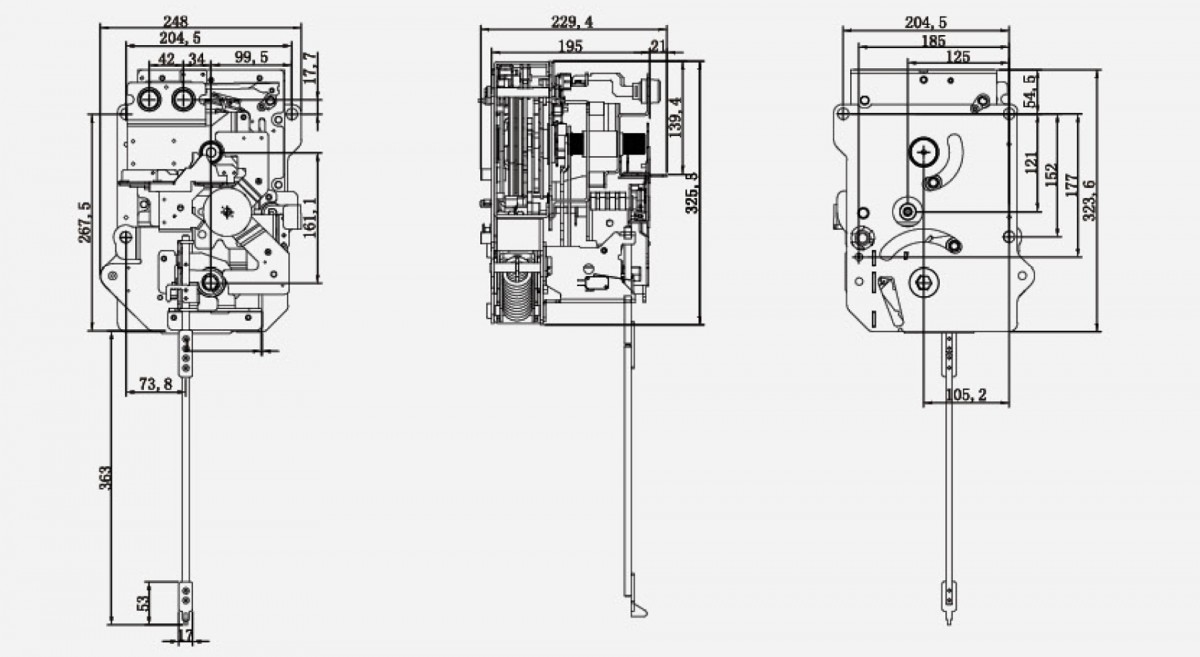
Actuator dimensions and installation sizes