


One,Equipment Model
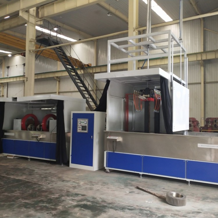
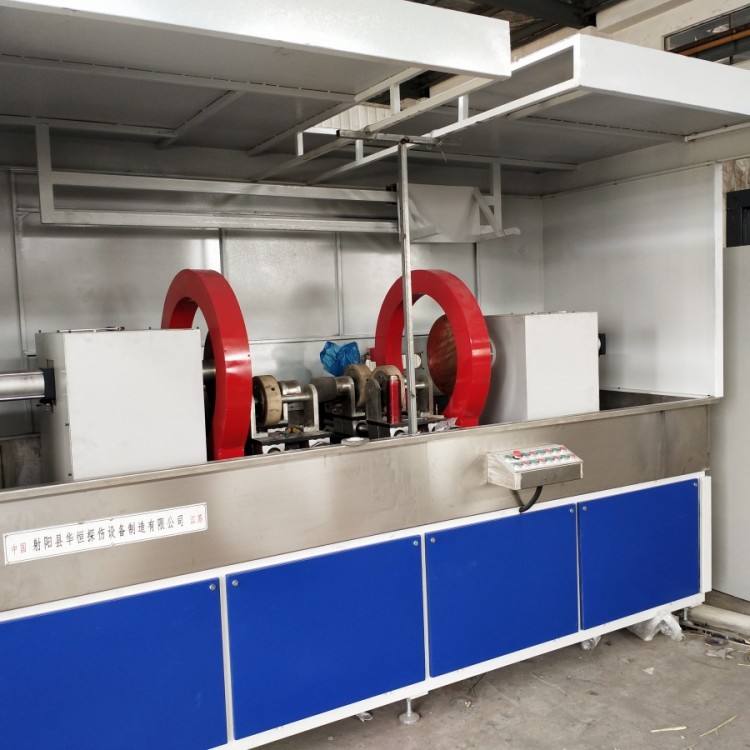
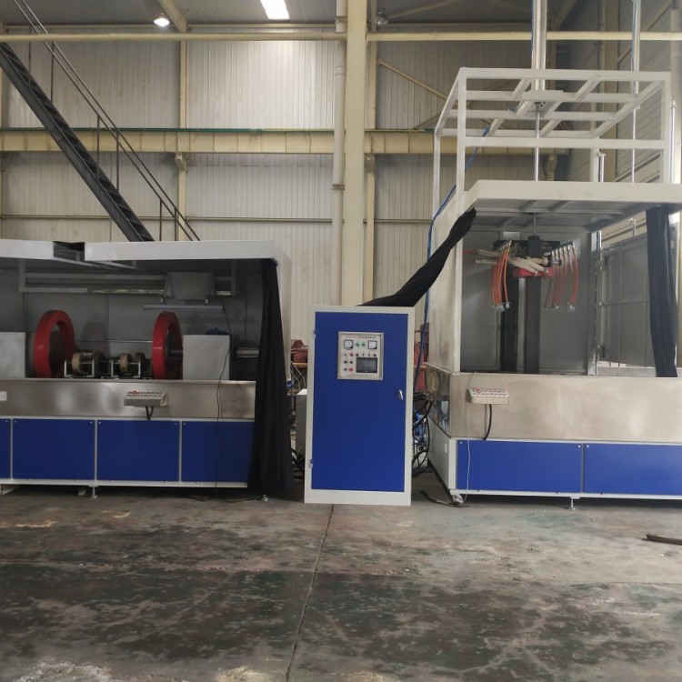
CDW-15000A Dual StationGear forFluorescent Magnetic Particle Inspection Machine
Section II: Basic Principles of Magnetic Particle Inspection
When a part made of ferromagnetic material is placed in a magnetic field, the fluctuating magnetic lines of force are attracted to and pass through the surface of the workpiece. If the magnetic lines are forced through a crack, magnetized magnetic domains within the workpiece will form small magnetic poles around the crack, and the magnetic lines will bypass this area to create a "leakage field." At this point, when magnetic particles are scattered over the surface of the part, they will accumulate at the crack to form magnetic marks, indicating the size and location of the part's defect. The color of the magnetic particles should contrast sharply with the color of the part's surface.
III. Application
This machine is designed based on the principle of magnetic particle inspection and in accordance with the requirements of GB/T8290-2011, and is suitable for parts made of various magnetic materials magnetized by AC. It can detect fine defects such as cracks and inclusions on the surface and near the surface of the parts caused by forging, quenching, grinding, and fatigue. The workpiece can be magnetized circumferentially, longitudinally, and in a composite manner. All the mechanical actions, such as clamping, spraying, magnetizing, and releasing, are controlled by a small industrial PC. Changing the PC's working program can alter the inspection process of the machine for the parts.
IV. Key Technical Performance Indicators
1. Axial magnetization current: AC: 0-15,000A continuously adjustable, voltage AC: 40V, with power-off phase controller
2. Vertical magnetization magnetic potential: AC: 0-32,000 AT continuously adjustable, voltage AC: 40V, with phase controller for power interruption
3. Magnetization Methods: Circumferential, Axial, Composite Magnetization
4. Workstation 1 electrode spacing: 0-1300mm
5. Magnetized Coil: Internal Diameter 300mm
6. Clamping Length: 200mm
7. Clamping Method: Pneumatic clamping, adjustable pressure ≥ 0.4 Mpa
8. Tail electrode box: Electrically powered mobile
9. Inspection Rhythm: 30S per piece (excluding detection time)
10. Detection Sensitivity: Clear display using Type A test piece (15/50) on workpiece surface.
11. Demagnetization Effect: Residual magnetism of the workpiece after demagnetization does not exceed 240 A/m (3GS)
12. Power Supply: Three-phase four-wire, 380V±10%, 50Hz, approximately 1750A
13. Workstation core rod spacing: 0-1000mm
14. Total Weight: Approximately 5 tons
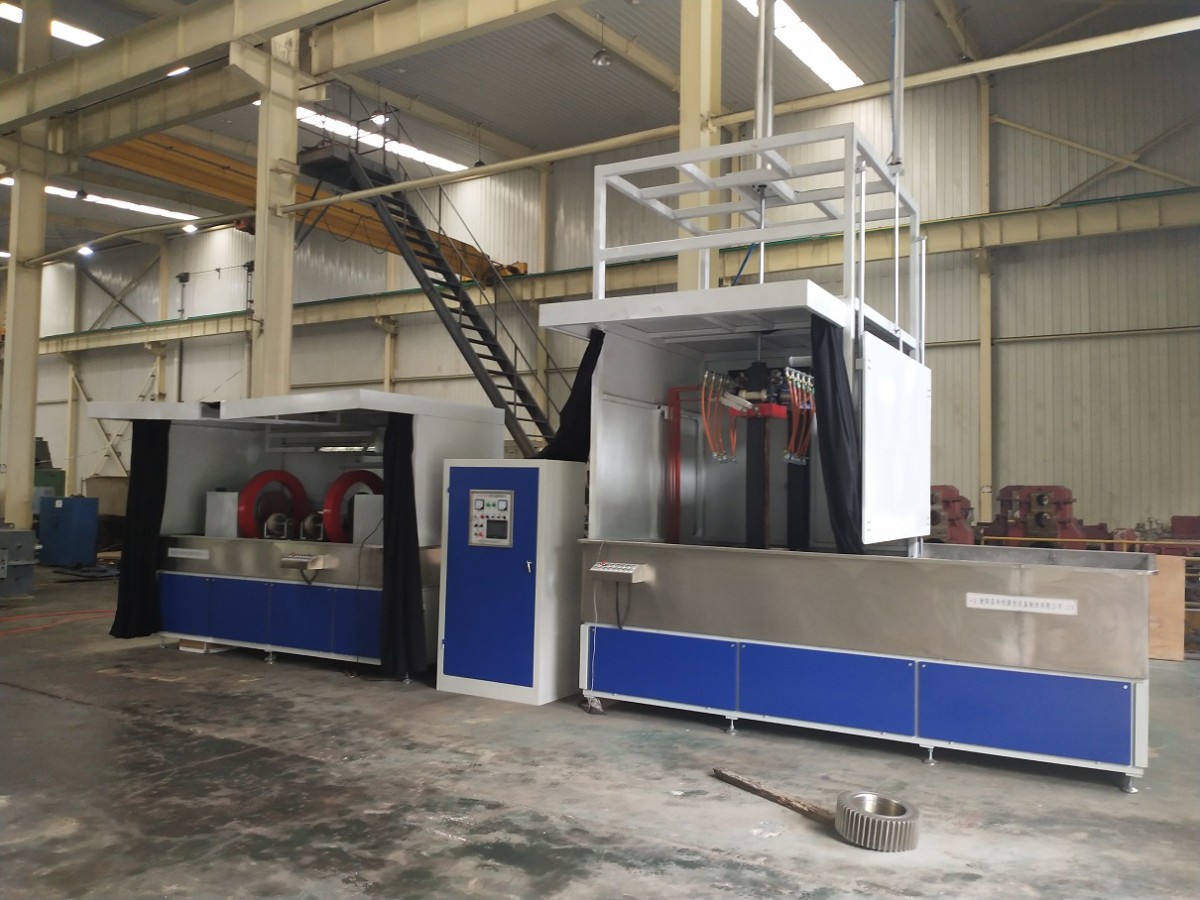
V. Composition and Structural Features of the Equipment
This machine features a fixed-type mechanical and electrical separation structure, primarily comprising the power cabinet, transformer cabinet, magnetization power supply control system, holding device station one, holding device station two, magnetization coil, magnetic suspension spray and recovery system, and the rotating mechanism.
The magnetized power system is housed within the power cabinet, while the electrical installation board is inside the bed frame, equipped with all electrical components, trigger control modules, PLCs, and thyristors, etc. The clamp electrode box assembly is made of cold-rolled steel焊接. The manual control panel is mounted in front of the fixed electrode box. The bed frame of the clamp assembly is constructed from channel steel and steel plate welding. The door panels are made of cold-rolled iron plates, with stainless steel sheets sealing the periphery and collecting liquid slots. Above the collecting liquid slots, there are left and right electrode boxes, closed-loop magnetic cores, two sets of magnetizing coils, and two spray systems. Below the collecting liquid slots, within the bed frame, there are main transformers, pneumatic components, and liquid storage tanks for magnetic suspension fluid, among others. The moving electrodes are adjusted for spacing by sliding on guides. The workpiece is clamped by the electrode head, which is directly powered by a cylinder. The main transformer coil, magnetizing coil, and circuit conductors are all made of copper bars and cables. The main transformer core is made of imported cold-rolled high-silicon silicon steel sheets. The liquid storage tank and collecting liquid slots are made of stainless steel plates. The liquid outlet of the magnetic suspension fluid tank is equipped with a filter mesh. The tank is equipped with a mixing pump and a suction pump at the top, featuring even mixing and high spray flow rates.
Section 6: Process Flow
Station 1:
Rotary selection feature:
There is rotation: loading → rotating spray → clamping → magnetization → secondary magnetization → release → rotating observation → demagnetization → unloading
Station 2:
Loading → Cart in → Rod insertion → Axial clamping → Rotation spray → Magnetization → Secondary magnetization → Axial release → Rod return → Rotation observation → Demagnetization → Cart out → Unloading
