

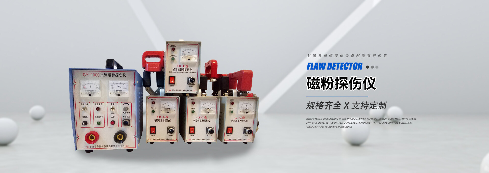


Section 1:Equipment Model
CJW-6000A Fluorescent Magnetic Particle Inspection Machine
II. Basic Principle of Magnetic Particle Inspection
When a part made of ferromagnetic material is placed in a magnetic field, the fluctuating magnetic field lines are attracted to and pass through the surface of the workpiece. If the magnetic field lines are forced through a crack, magnetized magnetic domains within the workpiece will form small magnetic poles around the crack, and the magnetic field lines will bypass this area.“Leakage magnetic field”When magnetic particles are applied to the surface of the part, they will accumulate at the crack locations to form magnetic marks, indicating the size and position of the part defects. The color of the magnetic particles should contrast sharply with the color of the part surface.
III. Application
The machine operates based on the principle of magnetic particle inspection.《GB/T8290-2011》Designed to meet the requirements, this is suitable for inspecting parts made from various magnetic materials magnetized by electromagnetic induction, capable of detecting minute defects such as cracks and inclusions on the surface and near-surface areas caused by forging, quenching, grinding, and fatigue. It allows for circumferential, longitudinal, and composite magnetization of the workpiece. A series of mechanical actions such as clamping, spraying, magnetizing, and releasing are all performed using small industrial...PC control allows for changing the PC work program, which in turn alters the inspection process of the equipment for parts.
IV. Main Technical Performance Indicators
1. Axial magnetization current: AC: 0-6000A continuously adjustable, voltage AC: 20V, with phase controller for power interruption
2. Vertical magnetization magnetic potential: AC: 0-24,000AT continuously adjustable, voltage AC: 24V, with power-off phase controller
3. Magnetization Methods: Circumferential, Axial, Composite Magnetization
4. Workstation 1 electrode spacing: 0-600mm
5. Magnetizing Coil: Inner Diameter 300mm
6. Clamping Travel: 50mm
7. Clamping Method: Pneumatic clamping, adjustable air pressure ≥ 0.4 Mpa
8. Tail electrode box: Electrically propelled mobile
9. Inspection Rhythm: 30S per piece (excluding detection time)
10. Detection Sensitivity: Clear display using Type A test piece (15/50) on the workpiece surface.
11. Demagnetization Effect: Residual magnetism of the workpiece after demagnetization does not exceed 240 A/m (3GS)
12. Power Supply: Three-phase four-wire, 380V±10%, 50Hz, approximately 80A
Total Weight: Approximately 1 ton
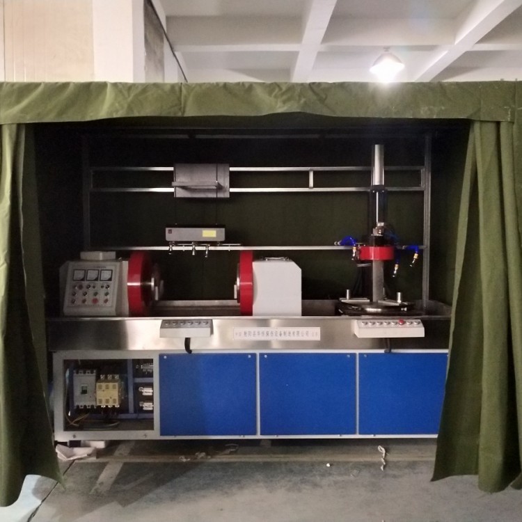
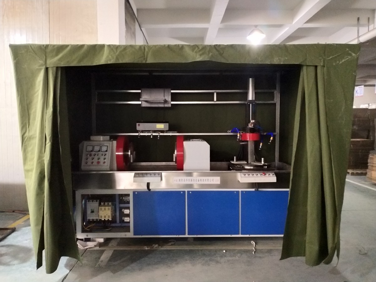
V. Composition and Structural Characteristics of the Equipment
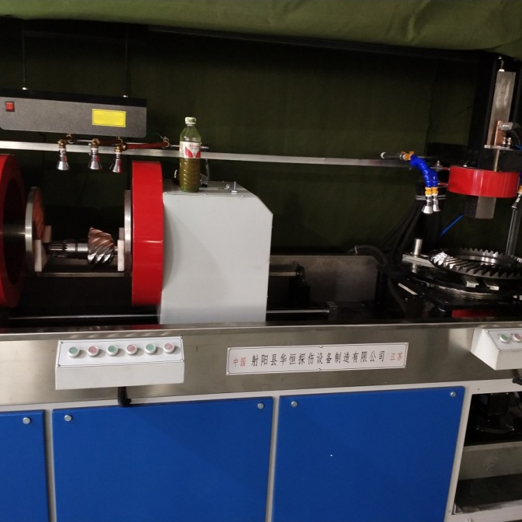
This machine features a fixed integrated mechanical and electrical structure, primarily comprising the power cabinet, magnetization power supply control system, holding device station one, holding device station two, magnetization coil, magnetic suspension fluid spraying and recovery system, and rotating mechanism.
The magnetized power system is placed beneath the bed frame, with the electrical installation panel inside the bed frame, fitted with all electrical components and the trigger control module.PLC and thyristor components, the clamp electrode box assembly is made of cold-rolled steel plate welding, the manual control panel is mounted in front of the fixed electrode box, the bed of the clamp device is made of channel steel and steel plate welding, the door panels are made of cold-rolled iron plates, the edges and collecting trays are sealed with stainless steel plates. Above the stainless steel collecting tray, there are left and right electrode boxes, a closed-loop magnetic yoke, two sets of magnetization coils, and two spray systems. Below the collecting tray, the bed interior houses the main transformer, pneumatic components, and a magnetic suspension liquid storage tank. The moving electrode adjusts the spacing between the two electrodes by sliding on the guide rail, and the workpiece is clamped by the electrode head powered directly by a cylinder. The main transformer coil, magnetization coil, and circuit conductors are all made of copper bars and cables, the main transformer core is made of imported cold-rolled high-silicon silicon steel sheets, the magnetic suspension liquid tank and collecting tray are made of stainless steel plates, the liquid outlet of the magnetic suspension liquid tank is equipped with a filter mesh. The upper part of the magnetic suspension liquid tank is equipped with a special mixing pump and a suction pump, featuring uniform mixing and high spray flow.
Section 6: Process Flow
Station 1:
Rotary selection feature:
Has rotation: LoadingClamp → Rotate to Spray → Magnetize → Secondary Magnetize → Rotate and Observe → Demagnetize → Release Clamp → Unload
No rotation: LoadingClamp → Spray → Magnetize → Secondary Magnetize → Release Clamp → Observe → Unload
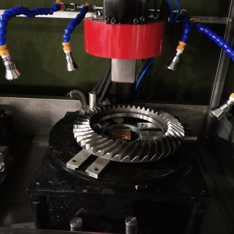
Station 2:
Supply materials→ Rod insertion → Rotate and spray → Magnetization → Secondary magnetization → Rod return → Rotate and observe → Demagnetization → Unloading
Section 7: Equipment Operating Environment and Installation Requirements
Relative humidity: Not greater than 85%.
2. Environmental Temperature: -10℃ to +40℃
3. Place the equipment on a level concrete surface during installation; no need to secure it to the ground.
Section 8: Magnetic Suspension Fluid Preparation
1. Preparation of Oil Magnetic Suspension SolutionPlease provide the Chinese content to be translated.OilMagnetic suspensionBe cautious of fire prevention; ensure fire extinguishers are available at the work site.)
AN-YC-2 Fluorescent Magnetic Powder, odorless kerosene.
AN-YC-2 Fluorescent Magnetic Powder 40g, odorless kerosene 25L, mix thoroughly. 1.5-2g/L
2. Preparation of Hydro-magnetic Suspension Solution
Fluorescent magnetic powder: 3-5g/L water
B. Non-fluorescent Magnetic Powder 10-20g/L Water
Section 9: Equipment Installation and Connection
During installation, simply place the machine on a level concrete surface. Open the left side panel, connect the power cord to the corresponding circuit breaker—three-phase, five-wire, do not connect incorrectly to prevent damage to the machine. (The neutral wire is connected to the neutral terminal, and the grounding terminal is located at the lower left corner of the machine tool.)
Ten. Equipment Usage
1. Jaws spacing adjustment
The spacing of the device's clamping jaws can beAdjustment electrically within 600mm.
(1) The right electrode can be freely positioned on the guide rail, adjusted to the exact clamping position required for the workpiece.
(2) The clamping speed can be adjusted by adjusting two throttle valves. The clamping cylinder is located inside the headbox on the left side of the bed frame. (The three-way valve, solenoid valve, and throttle valve are mounted on the left side of the bed frame.)
2. Selection of Magnetization Current
The magnetization current of the Zhou direction can generally be calculated as follows:
Continuous Method:I=10D-12D
Remanence measurement method:I=15D-20D
I - Ampere value; D - Sample diameter (mm)
Above are recommended values; if the specimen has special requirements,You can choose your own I & D relationship.
3. Magnetic Suspension Flow Rate Selection
The magnetic suspension fluid flow should be adjusted by the ball valve according to the surface area of the workpiece to ensure the workpiece surface is fully wetted within the automatic circulation time.
Eleven. Equipment Operation
Before operating this machine, please carefully read the relevant contents in the technical manual, familiarize yourself with its technical specifications and process standards, and ensure all wiring is correct before starting the machine.
The equipment selects station one or two based on the type of workpiece. Axial workpieces are processed at the left station, while ring-shaped workpieces are processed at the right station.
The equipment can be operated in two states.
Manual Mode Automatic Mode
1. Manual state operation
Establish connection“Power Supply”Switches, power indicator light on. The machine is in manual operation mode. Each time an operation button is pressed, it will produce the corresponding function output.
Note:
In manual mode“Work”When considering, it is important to note that the continuous magnetization time should not exceed2S, the interval between two magnetization cycles should not be less than 10S, as this is determined by the machine's set temporary load rate. Otherwise, it will cause the overheating of the whole machine's heating components, leading to unnecessary damage to the equipment.
2. Automated Operation
Press“Job”Keys, the entire unit will operate according to the programmed sequence.
This unit is “Automatic”Press in state“Reset”Push the button, the entire unit will cease operation. To resume, a restart is necessary.
3. The unit includes one foot switch.“Automatic”The foot switch is the start button while in operation mode.
Twelve: Lubrication
1. pneumatic component lubrication
To ensure that the oil misters in the three-in-one air source treatment unit are not lacking in lubricant, it is generally recommended to add oil once a month. Transformer oil or hydraulic oil should be used, and the condensation in the air filter should be drained regularly.
2、Clamp the electrode, and apply mechanical oil to the electrode sliding block once per revolution.
Section 13: Equipment Maintenance and Care
A. Maintenance and Care
1. This equipment should be placed and used in a clean, dry, well-ventilated environment.
2. No facilities generating strong electromagnetic interference should be present around the equipment.
3. Equipment operation, usage, and maintenance should be handled by designated personnel.
4. Clean and tidy the equipment before and after each shift.
5. The filter mesh in the magnetic suspension storage tank should be cleaned regularly.
6. Regularly inspect the pneumatic triple union, drain the accumulated water in the air filter, and regularly add lubricating oil to maintain good lubrication.
7. Regularly inspect the magnet suspension nozzle and remove impurities; check the spray valve and clear any debris inside the valve body.
8. Regularly inspect the protective grounding device to ensure good grounding.
9. The longitudinal magnet yoke coil should be kept clean; no impurities should be allowed to adhere to the gaps between the coils.
B. Inspection for Abnormal Conditions
1. Non-operational
Firstly, open the power cabinet and check if the air switch at the upper left corner of the distribution board is closed.
2. The machine fails to operate after startup
(1) Check whether it is“Automatic” Still“Manual”Status.
(2) Is the PC operating normally, and are there any alarm indicators?
3. No indication for current path
(Check if the quick melt unit on this route is damaged.
(2) Is the piece being clamped or held in place?
4. No Current
(1) Is there no product?
