


- AllProduct Category
-
Control Cabinet Division
Cable & Wire Division
Pressure Gauge Division
Digital Gauge Division
Validation Instrument Division
Level Measurement Division
Temperature Instrument Division
Transmitter Division
Flow Meter Division


详情描述
 |  |  | |||
| Anti-spray | Waterproof | Round plug/socket | Flange connector | Handle | Compensating conductor wire |
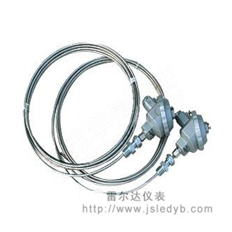
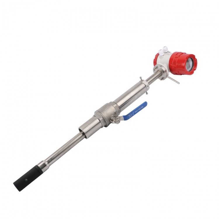
The working principle of installing a thermocouple involves welding two conductors with different compositions at both ends to form a closed loop. The directly measuring end is called the active end, while the terminal with the connecting wires is called the cold junction, also known as the reference end. When there is a temperature difference between the active end and the reference end, a thermal current is generated in the loop. By connecting a display instrument, the instrument will indicate the corresponding temperature value of the thermoelectric potential generated by the thermocouple.
The electromotive force (EMF) of the armored thermocouple increases with the rise in the measuring end temperature. The magnitude of the EMF is solely dependent on the material of the thermocouple conductors and the temperature difference between the two ends, and is unrelated to the length or diameter of the thermoelectric rods.
The structure principle of the armored thermocouple is that it is formed by conducting wire, high-insulation magnesia, and an outer 1Cr18Ni9Ti stainless steel sheath, which are pulled together integrally multiple times. The basic structure of the armored thermocouple product mainly consists of a terminal box, terminal connector, and the armored thermocouple itself, complemented by various installation and fixing devices.
Armored thermocouples are available in two types: insulated and grounded.
Basic Technical Specifications
| Category (Designation) | Fractional pitch | Outer Tube Diameter (d) | Common Temperature (°C) | Maximum Operating Temperature (°C) | Permitted deviation △t | |
Temperature Range (°C) | Tolerance range | |||||
| Nickel Chrome—Constantan WREK | E | ≥φ 3 | 600 | 700 | 0~700 | ± 2.5°C or ± 0.75%t |
| Nickel-Chromium — Nickel-Silicon WRNK | K | ≥φ 3 | 800 | 950 | 0~900 | ± 2.5°C or ± 0.75%t |
| Copper—Constantan WRCK | T | ≥φ 3 | 350 | 400 | <-200 | Not specified |
-40~350 | ± 1°C or ± 0.75%t | |||||
Note: 1. "t" refers to the absolute value of the temperature being measured.
2. T-type graduation products require consultation with the manufacturer for ordering.
Clad thermocouple thermal response time
At a step change in temperature, the time it takes for the thermocouple's output to change to 50% of that step is known as the thermal response time, represented by τ0.5.
Insulated Resistance
At an ambient air temperature of 20±1.5°C and a relative humidity not exceeding 80%, the insulation resistance between the thermocouple wire and the sheath of the insulated armored thermocouple should comply with the specifications in the following table.
Fiber Diameter (mm) | Test Voltage (V-DC) | Insulation Resistance (MΩ.m) |
1.5 | 50±10% | ≥ 1000 |
>1.5 | 500±10% | ≥ 1000 |
Flexible
The bendable radius of the armored thermocouple is not less than 5 times its outer diameter.
Sheathed thermocouple thermal response time
| Hot Response Time τ 0.5 second Tube diameter ( mm) | Shell Mount | Insulated |
3.0 | 0.6 | 1.2 |
4.0 | 0.8 | 2.5 |
5.0 | 1.2 | 4.0 |
6.0 | 2.0 | 6.0 |
8.0 | 4.0 | 8.0 |
Armored thermocouple standard specifications for outer diameter and nominal length
Armored thermocouple outer diameter d (mm) | ||||
φ 8 | φ 6 | φ 5 | φ 4 | φ 3 |
50 | 50 | 50 | 50 | 50 |
75 | 75 | 75 | 75 | 75 |
100 | 100 | 100 | 100 | 100 |
150 | 150 | 150 | 150 | 150 |
200 | 200 | 200 | 200 | 200 |
250 | 250 | 250 | 250 | 250 |
300 | 300 | 300 | 300 | 300 |
400 | 400 | 400 | 400 | 400 |
500 | 500 | 500 | 500 | 500 |
750 | 750 | 750 | 750 | 750 |
1000 | 1000 | 1000 | 1000 | 1000 |
1250 | 1250 | 1250 | 1250 | |
1500 | 1500 | 1500 | 1500 | |
2000 | 2000 | 2000 | 2000 | |
2500 | 2500 | 2500 | ||
3000 | 3000 | 3000 | ||
4000 | 4000 | 4000 | ||
5000 | 5000 | |||
7500 | 7500 | |||
10000 | 10000 | |||
15000 | ||||
Note: 1. The nominal total length L of the insulated armored thermocouple with diameter 3, shall not exceed 10,000mm.
2. For铠装热电偶withouter diameter d≤5mmandproducts with splash-proof or waterproof junction boxes, please note during installation that the exposed part of the thermocouple must be supported by brackets or other auxiliary supports to increase rigidity and ensure stability, preventing the junction box from swinging back and forth and damaging the thermocouple.
Structure
Structured form of armored thermocouple material
Work End (Hot End) Structure
Installation Fixed Type
The fixed installations are for user installation. Besides products without fixed installations, the armored thermocouple fixed installations include four structural forms: fixed sleeve type, movable sleeve type, fixed flange, and movable flange. The fixed sleeve type allows for a one-time installation, while the movable sleeve type allows for multiple installations.
| Armored thermocouple Outer Diameter d Pipe OD (mm) | φ 8 | φ 6 | φ 5 | φ 4 | φ 4 | φ 3 | φ 2 |
M | M16*1.5 | M12*1.5 | |||||
S | 22 | 19 | |||||
Note: Specifications within parentheses are generally not used; please place special order for these.
Sheathed thermocouple free end (terminal box) style
Terminal boxes are used for connecting the free ends of thermocouples to display instruments. They are currently available in various types, including simple, splash-proof, waterproof, handle-type, small terminal box, and compensating conductor styles.
Compensating conductor type
Splashproof
Waterproof
Handle-style
Mini junction box
Unfixed sheathed thermocouple
Name | Model | Pitch number | Work end form |
Single Nickel-Chromium - Constantan | WREK-101 WREK-121 WREK-131 WREK-181 WREK-187 WREK-191 | E | Insulated |
| WREK-102 WREK-122 WREK-132 WREK-182 WREK-188 WREK-192 | Snap-on shell | ||
Two strands of Nichrome - Constantan | WREK 2-121 WREK 2-131 | Insulated | |
| WREK 2-122 WREK 2-132 | Snap-on shell | ||
Single Nickel-Chromium - Nickel-Silicon | WRNK-101 WRNK-121 WRNK-131 WRNK-181 WRNK-191 WRNK-187 | K | Insulated |
| WRNK-102 WRNK-122 WRNK-132 WRNK-182 WRNK-188 WRNK-192 | Snap-on shell | ||
Two strands of Nichrome - Constantan | WRNK 2 -121 WRNK 2 -131 | Insulated | |
| WRNK 2 -122 WRNK 2 -132 | Snap-on shell | ||
Single Copper - Constantan | WRCK-101 WRCK-121 WRCK-131 WRCK-181 WRCK-191 WRCK-187 | T | Insulated |
| WRCK-102 WRCK-122 WRCK-132 WRCK-182 WRCK-188 WRCK-192 | Snap-on shell | ||
Two-strand Copper - Constantan | WRCK 2-121 WRCK 2-131 | Insulated | |
| WRCK 2-122 WRCK 2-132 | Snap-on Shell |
Note: Tube Outer Diameter d (mm): 3, 4, 5, 6, 8
Fixed bushing threaded type armored thermocouple
Name | Model | Pitch number | Work end style |
Single Nickel-Chromium - Constantan | WREK-201 WREK-221 WREK-231 WREK-281 WREK-291 | E | Insulated |
| WREK-202 WREK-222 WREK-232 WREK-282 WREK-292 | Snap-on shell | ||
Two strands of Nichrome - Constantan | WREK 2 -221 WREK 2 -231 | Insulated | |
| WREK 2 -222 WREK 2 -232 | Snap-on shell | ||
Single Nickel-Chromium - Nickel-Silicon | WRNK-201 WRNK-221 WRNK-231 WRNK-281 WRNK-291 | K | Insulated |
| WRNK-202 WRNK-222 WRNK-232 WRNK-282 WRNK-292 | Shell-mounted | ||
Nickel Chrome - Constantan | WRNK 2 -221 WRNK 2 -231 | Insulated | |
| WRNK 2 -222 WRNK 2 -232 | Shell Mount | ||
Single copper rod - Constantan | WRCK-201 WRCK-221 WRCK-231 WRCK-281 WRCK-291 | T | Insulated |
| WRCK-202 WRCK-222 WRCK-232 WRCK-282 WRCK-292 | Snap-on shell | ||
Two-strand Copper - Constantan | WRCK 2-221 WRCK 2-231 | Insulated | |
| WRCK 2-222 WRCK 2-232 | Snap-on shell |
Note: Tube outer diameter d (mm): φ3, φ4, φ5, φ6, φ8.
Removable bushing thread-type armored thermocouple
Name | Model | Pitch number | Work end form |
Single Nickel-Chromium - Constantan | WREK-301 WREK-321 WREK-331 WREK-391 WREK-381 WREK-387 # | E | Insulated |
| WREK-302 WREK-322 WREK-332 WREK-392 WREK-382 WREK-388 # | Snap-on shell | ||
Two-piece Nickel-Chromium - Constantan | WREK 2-321 WREK 2-331 | Insulated | |
| WREK 2-322 WREK 2-332 | Snap-on shell | ||
Single Nickel-Chromium - Nickel-Silicon | WRNK-301 WRNK-321 WRNK-331 WRNK-391 WRNK-381 WRNK-387 # | K | Insulated |
| WRNK-302 WRNK-322 WRNK-332 WRNK-392 WRNK-382 WRNK-388 | Snap-on Shell | ||
Nickel Chrome - Nickel Silicon | WRNK 2-321 WRNK 2-331 | Insulated | |
| WRNK 2-322 WRNK 2-332 | Snap-on shell | ||
Single Copper - Constantan | WRCK-301 WRCK-321 WRCK-331 WRCK-381 WRCK-391 WRCK-387 # | T | Insulated |
| WRCK-302 WRCK-322 WRCK-332 WRCK-382 WRCK-392 WRCK-388 # | Snap-on shell | ||
Two-piece copper - Constantan | WRCK 2-321 WRCK 2-331 | Insulated | |
| WRCK 2-322 WRCK 2-332 | Snap-on shell |
Note: Tube outer diameter d (mm): φ3, φ4, φ5, φ6, φ8.
Model #387 and #388 tubes have an outer diameter of φ3, φ4mm.
Fixed flange type armored thermocouple assembly
Name | Model | Pitch number | Work end form |
Single Nickel-Chromium - Constantan | WREK-401 WREK-421 WREK-431 WREK-481 WREK-491 | E | Insulated |
| WREK-402 WREK-422 WREK-432 WREK-482 WREK-492 | Shell Mount | ||
Nickel-Chromium - Constantan | WREK 2-421 WREK 2-431 | Insulated | |
| WREK 2-422 WREK 2-432 | Snap-on shell | ||
Single Nickel-Chromium - Nickel-Silicon | WRNK-401 WRNK-421 WRNK-431 WRNK-481 WRNK-491 | K | Insulated |
| WRNK-402 WRNK-422 WRNK-432 WRNK-482 WRNK-492 | Snap-on shell | ||
Two-strand Nichrome - Nickel Silicon | WRNK 2-421 WRNK 2-431 | Insulated | |
| WRNK 2-422 WRNK 2-432 | Snap-on shell | ||
Single Copper - Constantan | WRCK-401 WRCK-421 WRCK-431 WRCK-481 WRCK-491 | T | Insulated |
| WRCK-402 WRCK-422 WRCK-432 WRCK-482 WRCK-492 | Snap-on shell | ||
Two Strands of Copper - Constantan | WRCK 2-421 WRCK 2-431 | Insulated | |
| WRCK 2-422 WRCK 2-432 | Snap-on Shell |
Note: Tube outer diameter d (mm): φ3, φ4, φ5, φ6, φ8.
Removable sleeve type armor thermocouple with flange mounting
Name | Model | Tolerance grade | Work-end form |
Single Nickel-Chromium - Constantan | WREK-501 WREK-521 WREK-531 WREK-581 WREK-591 | E | Insulated |
| WREK-502 WREK-522 WREK-532 WREK-582 WREK-592 | Snap-on shell | ||
Two Nickel-Chromium - Constantan | WREK 2-521 WREK 2-531 | Insulated | |
| WREK 2-522 WREK 2-532 | Snap-on shell | ||
Single Nickel-Chromium - Nickel-Silicon | WRNK-501 WRNK-521 WRNK-531 WRNK-581 WRNK-591 | K | Insulated |
| WRNK-502 WRNK-522 WRNK-532 WRNK-582 WRNK-592 | Snap-on shell | ||
Dual Nickel-Chromium - Nickel-Silicon | WRNK 2-521 WRNK 2-531 | Insulated | |
| WRNK 2-522 WRNK 2-532 | Shell mount | ||
Single Copper - Constantan | WRCK-501 WRCK-521 WRCK-531 WRCK-581 WRCK-591 | T | Insulated |
| WRCK-502 WRCK-522 WRCK-532 WRCK-582 WRCK-592 | Snap-on shell | ||
Two-strand Copper - Constantan | WRCK 2-521 WRCK 2-531 | Insulated | |
| WRCK 2-522 WRCK 2-532 | Shell Mount |
Note: Tube outer diameter d (mm): φ3, φ4, φ5, φ6, φ8.
询价单

