


- AllProduct Category
-
Control Cabinet Division
Cable & Wire Division
Pressure Gauge Division
Digital Gauge Division
Validation Instrument Division
Level Measurement Division
Temperature Instrument Division
Transmitter Division
Flow Meter Division


详情描述
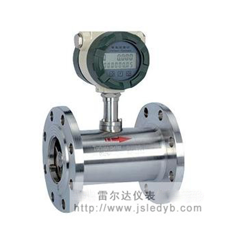
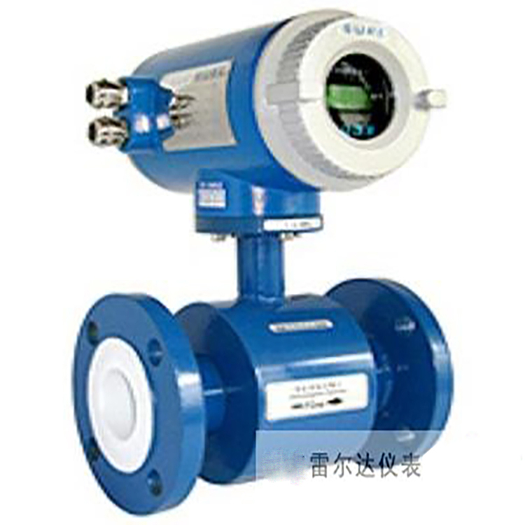
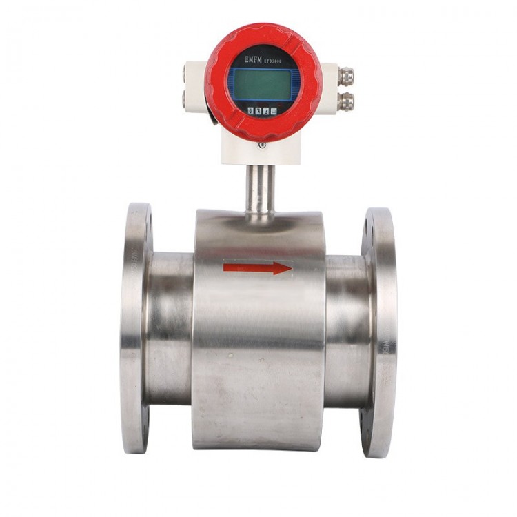
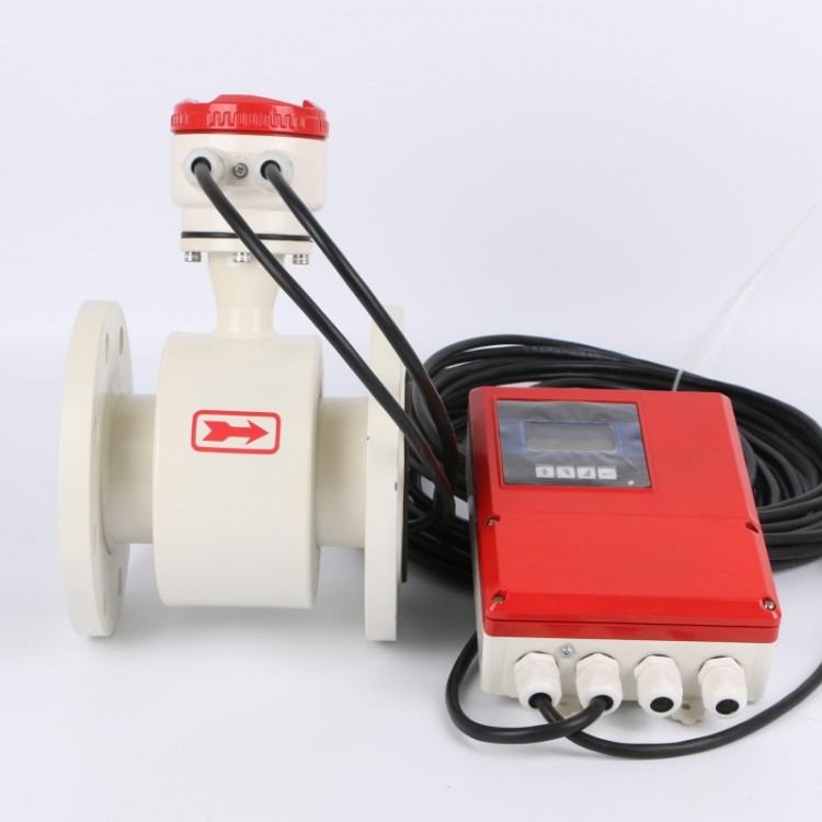
LRD-LWGYS Introduction
The LRD-LWGYS series of turbine flowmeters integrates advanced technology from both domestic and international flow measurement instruments, optimized for simplicity, lightness, high precision, excellent reproducibility, and sensitive response. Installation and maintenance are straightforward.The next-generation turbine flowmeter, featuring ease of use and other advantages, is widely used for measuring liquids in closed pipes that are non-corrosive to stainless steel grades 1Cr18Ni9Ti and 2Cr13, as well as alumina Al2O3 and hard alloy, and are free of fibers and particles. The liquids should have a kinematic viscosity less than 5×10^-6 m²/s at working temperatures. For liquids with a kinematic viscosity greater than 5×10^-6 m²/s, the flowmeter can be used after real-liquid calibration. When paired with a display instrument with special functions, it can also perform quantitative control and overfill alarms, making it an ideal instrument for flow measurement and energy conservation.
LRD-LWGYS Product Features
 High precision, typically up to ±1%R, ±0.5%R, with high-precision models reaching ±0.2%R.
- Good repeatability, short-term repeatability can reach 0.05% to 0.2%. Due to its excellent repeatability, high precision can be achieved through regular calibration or online calibration.
The flowmeter of choice for trade settlement. - Output pulse frequency signal, suitable for total quantity measurement and computer connection, no zero-point drift, strong anti-interference ability.
- Achieve a high-frequency signal (3-4 kHz) with strong signal resolution.
- Variety of sizes, medium to large diameters up to 1:20, small diameters at 1:10.
- Compact and lightweight, easy to install and maintain, with high throughput capacity.
- Suitable for high-pressure measurement; no need to drill holes on the instrument body, easy to manufacture high-pressure models.
- Specialized sensors come in various types and can be custom-designed to meet specific user requirements, such as low-temperature models, bidirectional types, downhole models, and mixed-sand specialized sensors, among others.
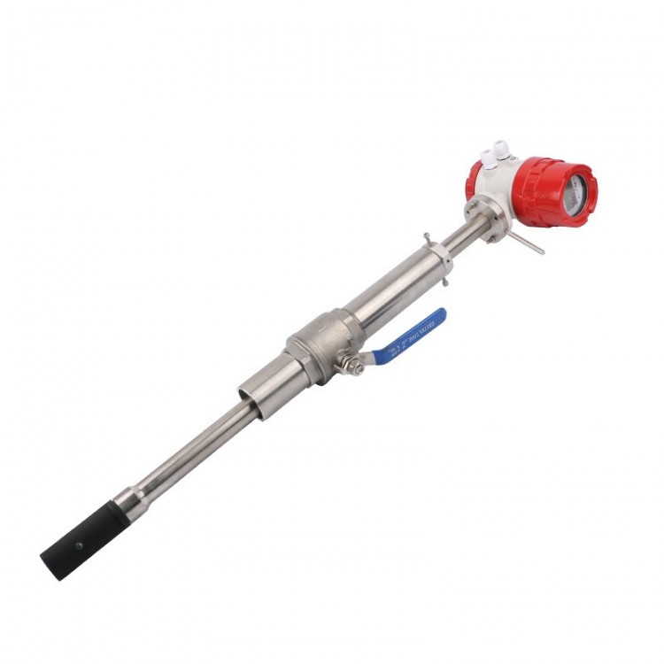
- Insertable design for large diameter measurements; minimal pressure loss; low price; non-stop flow extraction; easy installation and maintenance.
LRD-LWGYS Technical Specifications
Standard of Implementation
Turbine Flow Sensor (JB/T9246-1999)
Instrument Diameter (mm) & Connection Type
4, 6, 10, 15, 20, 25, 32, 40, 50, 65, 80 sizes feature threaded connections
Accuracy Grade
±1%R, ±0.5%R, ±0.2%R (Special Order)
Range Ratio
1:10;1:15;1:20
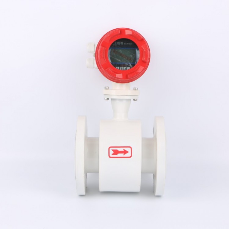
Sensor Material
304 stainless steel, 316 (L) stainless steel
Terms of Use
Medium Temperature: -20℃ to +120℃; Environmental Temperature: -20℃ to +60℃
Relative humidity: 5% to 90% Atmospheric pressure: 86Kpa to 106KpaSignal Output Function
Pulse Signal, 4-20mA Signal
Communication Output Function
RS-485 communication, HART protocol
Work Power Supply
Signal Line Interface
Basic Type: Hausmann connector or with a 3-core cable; Explosion-proof Type: Internal thread M20*1.5
Intrinsically Safe Rating
Exia II CT4 or Exd IIB T6
Protection Level
IP65 or higher ( customizable )
External Power Supply: +24VDC ±15%, ripple ≤ ±5%, suitable for 4-20mA output, pulse output, RS485, etc.
Internal Power Supply: 1 set of 3.0V 10AH lithium battery, which can operate normally at battery voltages between 2.0V and 3.0V.
LRD-LWGYS Measuring Range and Working Pressure
Instrument Diameter
(mm)
Normal traffic range
(m³/h)
Expand traffic range
(m³/h)
Default installation method and pressure rating
Optional installation methods and default pressure rating
Specialized pressure rating
(MPa)
DN4
0.04~0.25
0.04~0.4
Threaded installation, 6.3 MPa
Flange installation, 2.5 MPa
12、16、25
DN6
0.1~0.6
0.06~0.6
Threaded installation, 6.3 MPa
Flange Installation, 2.5 MPa
12、16、25
DN10
0.2~1.2
0.15~1.5
Threaded installation, 6.3 MPa
Flange Installation, 2.5 MPa
12、16、25
DN15
0.6~6
0.4~8
Threaded installation, 6.3 Mpa
Flange Installation, 2.5 MPa
4.0、6.3、12、16、25
DN20
0.8~8
0.45~9
Threaded installation, 6.3 MPa
Flange Installation, 2.5 MPa
4.0、6.3、12、16、25
DN25
1~10
0.5~10
Threaded installation, 6.3 MPa
Flange Installation, 2.5 MPa
4.0、6.3、12、16、25
DN32
1.5~15
0.8~15
Threaded installation, 6.3 MPa
Flange Installation, 2.5 MPa
4.0、6.3、12、16、25
DN40
2~20
1~20
Threaded installation, 6.3 MPa
Flange installation, 2.5 MPa
4.0、6.3、12、16、25
DN50
4~40
2~40
Flange Installation, 2.5 MPa
Bolted connections, 6.3 MPa
4.0、6.3、12、16、25
DN65
7~70
4~70
Flange Installation, 1.6 MPa
Bolted connection, 6.3 MPa
4.0、6.3、12、16、25
DN80
10~100
5~100
Flange Installation, 1.6 MPa
Threaded connections, 6.3 MPa
4.0、6.3、12、16、25
DN100
20~200
10~200
Flange Installation, 1.6 MPa
4.0、6.3、12、16、25
DN125
25~250
13~250
Flange Installation, 1.6 MPa
2.5、4.0、6.3、12、16
DN150
30~300
15~300
Flange Installation, 1.6 MPa
2.5、4.0、6.3、12、16
DN200
80~800
40~800
Flange Installation, 1.6 MPa
2.5、4.0、6.3、12、16
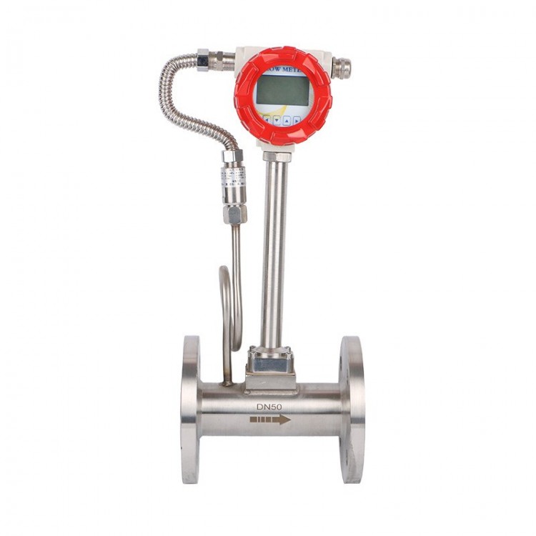
LRD-LWGYS Installation Dimensions
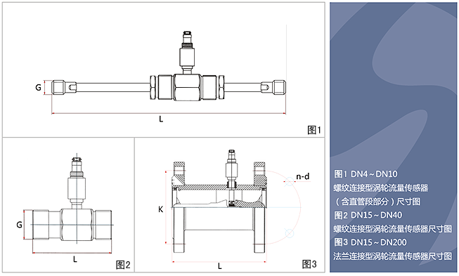
Sensor installation methods vary by specification, utilizing either threaded or flanged connections. Installation methods are depicted in Figures 1, 2, and 3, with installation dimensions listed in the table below:
Nominal Bore Diameter (mm) L(mm)
G
K(mm)
D(mm)
Number of Holes (n)
4
225
G1/2
6
225
G1/2
10
345
G1/2
15
75
G1
Φ65
Φ14
4
20
80
G1
Φ75
Φ14
4
25
100
G5/4
Φ85
Φ14
4
32
140
G2
Φ100
Φ14
4
40
140
G2
Φ110
Φ18
4
50
150
G5/2
Φ125
Φ18
4
65
170
Φ145
Φ18
4
80
200
Φ160
Φ18
8
100
220
Φ180
Φ18
8
125
250
Φ210
Φ18
8
150
300
Φ240
Φ22
8
200
360
Φ295
Φ22
12
LRD-LWGYS Product Categories
Technical Items Technical Specifications Technical Specifications Technical Specifications Instrument Model LRD-LWGYS-N LRD-LWGYS-A LRD-LWGYS-B LRD-LWGYS-C Signal Output Pulse 4-20mA No content provided. 4-20mA/Pulse Power Supply +24VDC±15% +24VDC±15% 24VDC±15% 24VDC±15% Lithium-ion Battery 24VDC±15% Precision Grade 1.0-0.5 grades 1.0 to 0.5 grade 1.0-0.5 grades Measurement Range Standard Range Standard Range Standard Range or Extended Range Monitor No content provided. No content provided. Available Communication Interface N/A No content provided. No content provided. Optional RS485 Communication Protocol N/A No content provided. No content provided. Moubus HART Instrument Material Stainless Steel Stainless Steel Stainless Steel Intrinsically Safe Rating N/A ExdIIBT6 or ExiaIICT4 ExdIIBT6 or ExiaIICT4 Protection Grade IP60 IP65 IP65 Total Power Consumption < 1W < 1W < 1W Instrument passage DN4~DN250 DN4~DN250 DN4~DN250 Medium Temperature -20℃~120℃ -20℃~120℃ -20℃~120℃ Ambient Temperature -30℃~60℃ -30℃~60℃ -30℃~60℃
询价单

