
How to Properly Choose an Electric Valve
What is an Electric Valve?
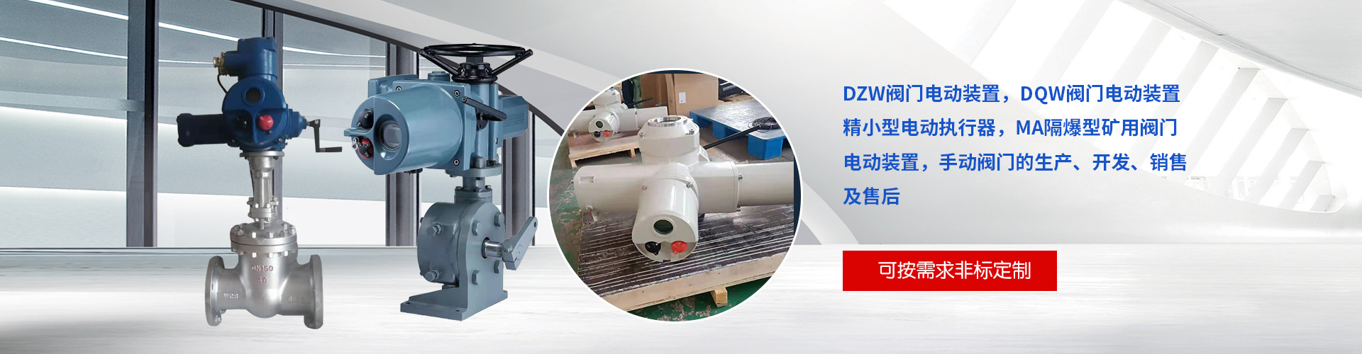
Electric valves, simply put, are controlled by electric actuators to open and close the valves. They are divided into two parts: the upper part being the electric actuator and the lower part the valve. They can also be referred to as air conditioning valves.
Electromagnetic valves are high-end products in the field of automatic valves. They not only perform on/off functions, but also, the regulating electromagnetic valves can adjust valve positions. The stroke of the electric actuators can be divided into two types: 90° angular stroke and straight stroke. Special requirements can also be met for 180°, 270°, and 360° full strokes. Electric actuators with angular stroke are used with angular stroke valves to control the flow of fluids in the pipeline by rotating within 90°; while electric actuators with straight stroke are used with straight stroke valves to control the up and down movement of the valve plate, thereby controlling the flow of fluids in the pipeline.
Technical Principles
Electromagnetic valves are typically connected to electric actuators and valves, becoming an electric valve after installation and tuning. They use electrical power to drive the electric actuator, controlling the valve's opening and closing or adjustment actions, thereby achieving the purpose of switching or regulating the medium in the pipeline.
Electromagnetic valves are typically driven by motors, with opening and closing actions requiring a certain amount of time and capable of adjustment. They are more resistant to voltage surges. Electromagnetic valves are designed for quick opening and closing, commonly used in low flow and low-pressure applications where high switching frequencies are required; conversely, electric valves are used in these scenarios. The opening degree of electric valves can be controlled, with states including fully open, fully closed, and semi-open/semi-closed, allowing for the regulation of flow through the pipeline medium, which electromagnetic valves cannot achieve.
The three-wire solenoid valve features F/R/N lines, with F representing the forward (or open) action control line, R representing the reverse (or close) action control line, and N representing the ground line. The solenoid valve is a type of electric valve; it uses the magnetic field generated by the electromagnetic coil to pull the valve core, thereby changing the valve body's open/close state. When the coil is de-energized, the valve core retracts under the pressure of the spring.
What Types of Electric Valves Are There?
1. Electric valves can be categorized by their valve position function into: on/off electric valves and regulating electric valves.
2. The valves can be categorized by their valve type: electric ball valves and electric butterfly valves.
3. By valve body shape, they can be further categorized into: standard electric valves and micro electric valves.
4. Electric valves are commonly of switch-type and regulating-type.
5. Connections are categorized into three-wire and two-wire systems, with large diameters predominantly using three-wire systems, while smaller diameters may have both two-wire and three-wire configurations.
Operating Environment for Electric Valves
Electric valves, in addition to considering pipeline parameters, should also pay special attention to their working environmental conditions. This is because the electric mechanism within electric valves is a mechanical and electrical device, whose operating conditions are greatly affected by the environmental factors. Typically, the working environments for electric valves include the following:
Indoor installation or outdoor use with protective measures.
2. Outdoor installation exposed to erosion from wind, sand, rain, dew, and sunlight.
3. Flammable, explosive gas or dust environments.
4. Wet tropical and dry tropical environments
5. The pipeline medium temperature exceeds 480℃.
6. Environmental temperatures below -20℃.
7. Susceptible to flooding or immersion.
Environmental with radioactive materials (nuclear power plants and radioactive material test facilities)
9. Environment aboard vessels or shipyards (with salt fog, mold, and humidity)
10. Situations with severe vibration.
11. Locations prone to fires.
For the electric valves in the aforementioned environment, the structures, materials, and protective measures of their electric devices vary. Therefore, the corresponding electric device for the valve should be selected based on the above working environment.
Functional Requirements for Electric Valves
In compliance with engineering control requirements, the control function of electric valves is performed by electric actuators. The purpose of using electric valves is to achieve non-manual electrical or computer control for the opening, closing, and adjustment of the valves. The use of electric actuators is no longer solely for labor savings. Due to significant differences in functionality and quality among manufacturers, the selection of electric actuators and the valves they are paired with is equally important for the project.
Electromagnetic actuators are indispensable equipment for valve programming, automation, and remote control, with their movement process controlled by stroke, torque, or axial thrust. As the working characteristics and utilization rate of electromagnetic actuators depend on the type of valve, the operational specifications of the device, and the position of the valve on the pipeline or equipment, selecting the correct electromagnetic actuator is crucial to prevent overloading (operational torque exceeding control torque).
Consider the following points when selecting electric valves:
1. Torque Requirement: Torque is the most critical parameter in selecting an electric valve actuator. The output torque of the electric actuator should be 1.2 to 1.5 times the maximum torque required for valve operation.
2. The main structure of the electric actuation unit for thrust valves includes two types: one does not have a thrust disk, directly outputting torque; the other is equipped with a thrust disk, converting the output torque through the thrust rod nut in the thrust disk to produce thrust.
3. The number of rotations of the output shaft of the valve electric actuator is related to the nominal bore diameter of the valve, the screw pitch of the valve stem, and the number of threads per thread. It should be calculated using the formula M = H / (ZS), where M is the total number of rotations the electric actuator should meet, H is the valve opening height, S is the pitch of the valve stem drive thread, and Z is the number of threads per thread.
4. For multi-revolution through-bolt valves, if the maximum valve rod diameter that the electric device allows cannot pass through the valve rod of the valve, it cannot be assembled into an electric valve. Therefore, the inner diameter of the hollow output shaft of the electric device must be larger than the outer diameter of the through-bolt valve rod. For part-revolution valves and blind-rod valves in multi-revolution valves, although the issue of valve rod diameter passage does not need to be considered, it is still necessary to carefully consider the size of the valve rod diameter and keyway during selection to ensure normal operation after assembly.
5. If the opening and closing speed of the output speed valve is too fast, it is prone to water hammer phenomena. Therefore, the appropriate opening and closing speed should be selected based on different operating conditions.
6. Electric valve actuators have specific requirements, including the ability to limit torque or axial force. Typically, electric valve actuators use torque-limiting couplings. Once the specifications of the electric actuator are determined, so is the controlled torque.
