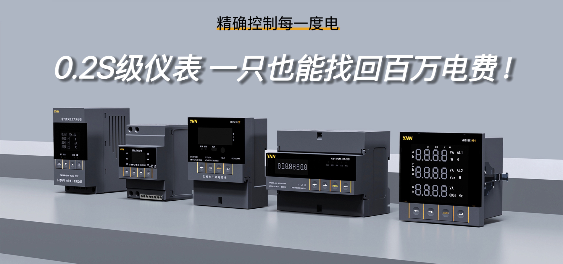

Optional Instrument Types
(1) Multi-functional Electric Power Meters (Optional 4G) (2) Multi-functional Rate Electric Power Meters (Optional 4G)
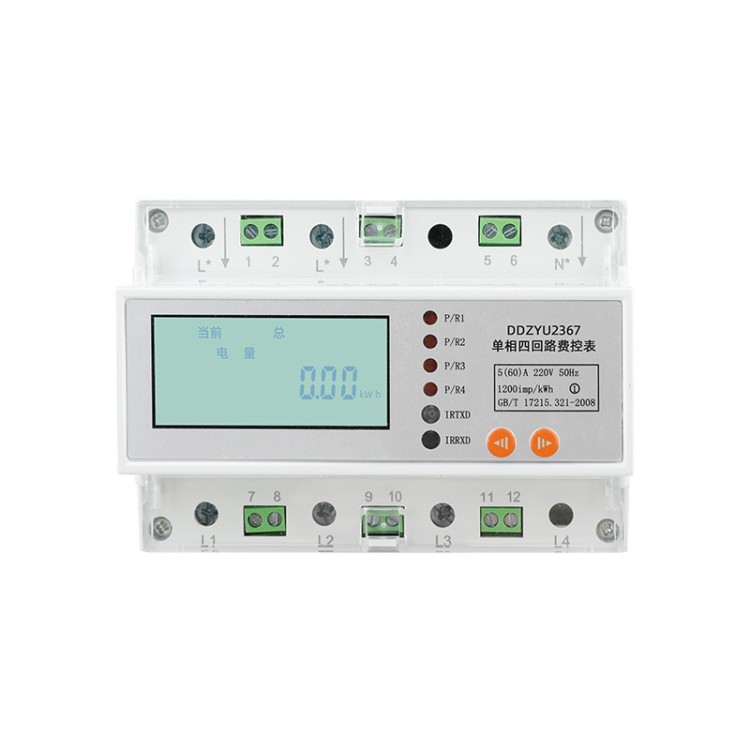
(3) Multi-functional Power Consumption Control Meters (optional with dual tariff or 4G) (4) Pre-paid Multi-functional Power Meters (pre-paid through the platform)
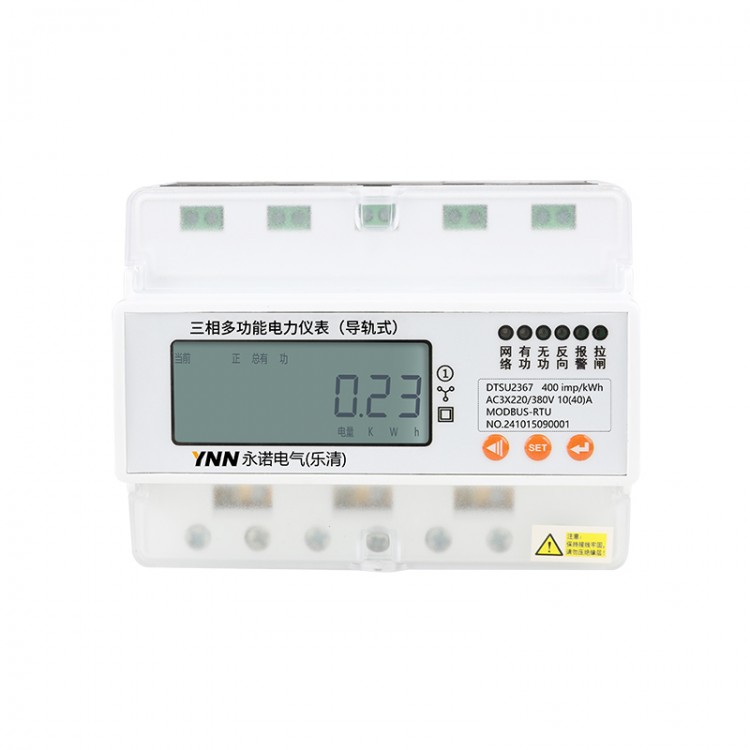
Real-time Monitoring: Voltage, Current, Power, Frequency, Power Factor, Energy
LCD Liquid Crystal Display
Communication: 1-way RS485 communication function, MODBUS-RTU protocol or DLT645-2007 protocol
Installation Method: Track installation, enhancing work efficiency
Power Failure Protection: Data is automatically saved upon power failure, no records lost.
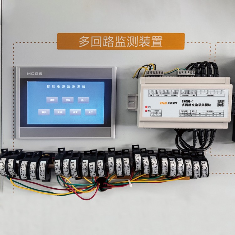
Application Fields: Industrial Manufacturing, Commercial Buildings, Integrated Plants, Substations, Public Utilities, etc.
Customization: We offer logo, appearance, and feature customization services for businesses.
Product Specifications
| Product Line | Precision Grade | Rated Voltage | Current Specifications | Pulse Constant |
| Track-type multi-functional electrical meter | 1.0 | AC220V | 5(20)A | 1600imp/kWh |
| 10(40)A | ||||
| 15(60)A |
Technical Specifications
| Project | Technical Specifications |
| Electrical Energy Precision Grade | Grade 1.0 |
| Electrical Energy Measurement Range | 0~99999.9KWh |
| Rated Voltage | AC 220V |
| Current specification | 5(20)A、10(40)A、15(60)A |
| Working Voltage | Normal: 0.9~1.1 Un; Limit: 0.7~1.2 Un |
| Reference Frequency | 45~65Hz |
| Starting Current | 0.004Ib |
| Power Consumption | ≤5VA |
| Pulse Output | Pulse Width: 80 ± 20 ms Optocoupler Isolated Output |
| Digital Communication | RS485 Interface, Modbus RTU or DLT645-2007 Protocol |
| Temperature Range | -10℃~+55℃ |
| Relative Humidity | ≤95% No Condensation |
| Dimensions | 36x100x66 |
Feature Description
Electricity Metering
Positive active energy measurement function.
2 Real-time Measurement
Can measure real-time voltage, current, active power, power factor, etc. Measurement error (reference error) does not exceed ±1%.
Remote Switching (Optional)
Built-in load switch; the electricity meter can output signals to control the load switch, compatible with 4G/485 communication, enabling remote manual opening and closing of the switch.
4 LED Indication, Pulse Signal Output
The electrical panel is equipped with 3 LED indicator lights: circuit breaker, pulse, and network indicator.
5. Power pulse
Indicate pulse output, power pulse constant of 1600 imp/kWh.
6. 4G Signal Indicator
Indicate whether the electrical energy meter is connected to the network, specifically as follows:
The indicator blinks, indicating entry into the smart networking mode; the indicator remains steady without blinking, meaning the electricity meter is online, paired, and confirmation of an open internet connection allows for remote management.
7. Alarm Indicator
a) Constant illumination indicates that the electricity meter has been disconnected.
8. 4G Communication (Optional)
The built-in 4G communication module ensures that whether it communicates or not will not affect the performance, operating parameters, or normal measurement of the electric meter.
After the electrical energy meter is powered on, the 4G module automatically searches for and connects to the nearest base station to access the 4G network. If the signal inside the building is weak, an external antenna can be connected to extend to an open area with better signal reception, facilitating the meter's network connection.
9. 485 Communication
The energy meter features a 485 communication interface, which can communicate with the meter individually via the 485 terminal, or connect to a collector through the 485 terminal. Damage to the interface does not affect the normal operation of other interfaces. The communication interface and the internal circuit of the energy meter are optically isolated, with a failure protection circuit in place.
10. Remote Functionality
Once successfully connected to the network, the electricity meter is linked to our company's server, working in conjunction with our backend system to enable multiple remote functions, primarily including:
a) Admin PC, wireless remote meter reading, switch opening/closing, remote management
b) Customers can recharge remotely through the WeChat mini-program and receive push notifications via the official account.
Dimensions and wiring diagram
1. Option 1: Bottom-in, Bottom-out; Option 2: Top-in, Bottom-out. Please specify at time of order.

Note:
Tighten the screws securely when wiring to prevent the instrument from malfunctioning due to poor contact.
2. Wiring with push-pull switch function is only available for bottom-to-bottom entry and exit.


Optional Instrument Types
(1) Multi-functional Electric Power Meters (Optional 4G) (2) Multi-functional Rate Electric Power Meters (Optional 4G)
(3) Multi-functional Power Consumption Control Meters (optional with dual tariff or 4G) (4) Pre-paid Multi-functional Power Meters (pre-paid through the platform)
Real-time Monitoring: Voltage, Current, Power, Frequency, Power Factor, Energy
LCD Liquid Crystal Display
Communication: 1-way RS485 communication function, MODBUS-RTU protocol or DLT645-2007 protocol
Installation Method: Track installation, enhancing work efficiency
Power Failure Protection: Data is automatically saved upon power failure, no records lost.
Application Fields: Industrial Manufacturing, Commercial Buildings, Integrated Plants, Substations, Public Utilities, etc.
Customization: We offer logo, appearance, and feature customization services for businesses.
Product Specifications
| Product Line | Precision Grade | Rated Voltage | Current Specifications | Pulse Constant |
| Track-type multi-functional electrical meter | 1.0 | AC220V | 5(20)A | 1600imp/kWh |
| 10(40)A | ||||
| 15(60)A |
Technical Specifications
| Project | Technical Specifications |
| Electrical Energy Precision Grade | Grade 1.0 |
| Electrical Energy Measurement Range | 0~99999.9KWh |
| Rated Voltage | AC 220V |
| Current specification | 5(20)A、10(40)A、15(60)A |
| Working Voltage | Normal: 0.9~1.1 Un; Limit: 0.7~1.2 Un |
| Reference Frequency | 45~65Hz |
| Starting Current | 0.004Ib |
| Power Consumption | ≤5VA |
| Pulse Output | Pulse Width: 80 ± 20 ms Optocoupler Isolated Output |
| Digital Communication | RS485 Interface, Modbus RTU or DLT645-2007 Protocol |
| Temperature Range | -10℃~+55℃ |
| Relative Humidity | ≤95% No Condensation |
| Dimensions | 36x100x66 |
Feature Description
Electricity Metering
Positive active energy measurement function.
2 Real-time Measurement
Can measure real-time voltage, current, active power, power factor, etc. Measurement error (reference error) does not exceed ±1%.
Remote Switching (Optional)
Built-in load switch; the electricity meter can output signals to control the load switch, compatible with 4G/485 communication, enabling remote manual opening and closing of the switch.
4 LED Indication, Pulse Signal Output
The electrical panel is equipped with 3 LED indicator lights: circuit breaker, pulse, and network indicator.
5. Power pulse
Indicate pulse output, power pulse constant of 1600 imp/kWh.
6. 4G Signal Indicator
Indicate whether the electrical energy meter is connected to the network, specifically as follows:
The indicator blinks, indicating entry into the smart networking mode; the indicator remains steady without blinking, meaning the electricity meter is online, paired, and confirmation of an open internet connection allows for remote management.
7. Alarm Indicator
a) Constant illumination indicates that the electricity meter has been disconnected.
8. 4G Communication (Optional)
The built-in 4G communication module ensures that whether it communicates or not will not affect the performance, operating parameters, or normal measurement of the electric meter.
After the electrical energy meter is powered on, the 4G module automatically searches for and connects to the nearest base station to access the 4G network. If the signal inside the building is weak, an external antenna can be connected to extend to an open area with better signal reception, facilitating the meter's network connection.
9. 485 Communication
The energy meter features a 485 communication interface, which can communicate with the meter individually via the 485 terminal, or connect to a collector through the 485 terminal. Damage to the interface does not affect the normal operation of other interfaces. The communication interface and the internal circuit of the energy meter are optically isolated, with a failure protection circuit in place.
10. Remote Functionality
Once successfully connected to the network, the electricity meter is linked to our company's server, working in conjunction with our backend system to enable multiple remote functions, primarily including:
a) Admin PC, wireless remote meter reading, switch opening/closing, remote management
b) Customers can recharge remotely through the WeChat mini-program and receive push notifications via the official account.
Dimensions and wiring diagram
1. Option 1: Bottom-in, Bottom-out; Option 2: Top-in, Bottom-out. Please specify at time of order.
Note:
Tighten the screws securely when wiring to prevent the instrument from malfunctioning due to poor contact.
2. Wiring with push-pull switch function is only available for bottom-to-bottom entry and exit.
| 品牌: | Yong诺Electrical |
| Brand: | Yong诺Electrical |
| Region: | National |
| Model: | Customizable |
| 单价: | 电议 |
| 最小起订Quantity: | |
| 供货总Quantity: | |
| 有效期至: | 长期有效 |
| 最后更新: | 2025-04-29 13:11 |