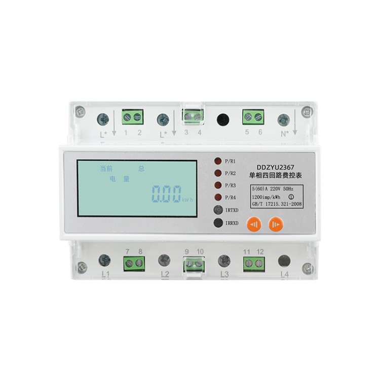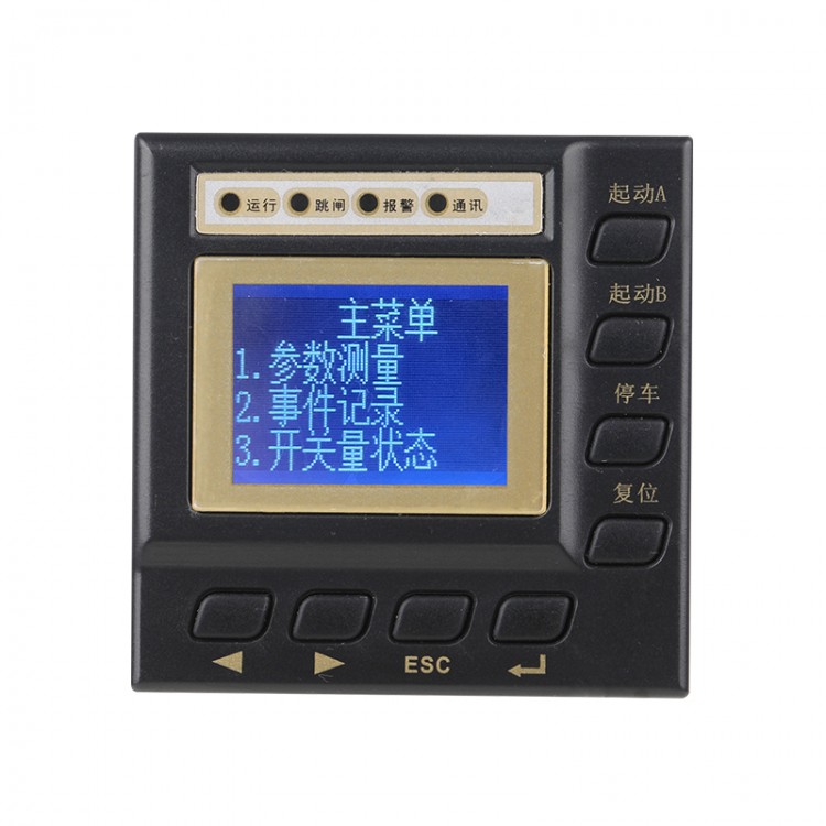

Real-time Monitoring: Voltage, Current, Power, Frequency, Power Factor, Energy
LCD Liquid Crystal Display
Communication: 1-way RS485 communication function, MODBUS-RTU protocol or DLT645-2007 protocol
Installation Method: Rail mounting, enhancing work efficiency
Power Failure Protection: Data is automatically saved and records are not lost after power failure.
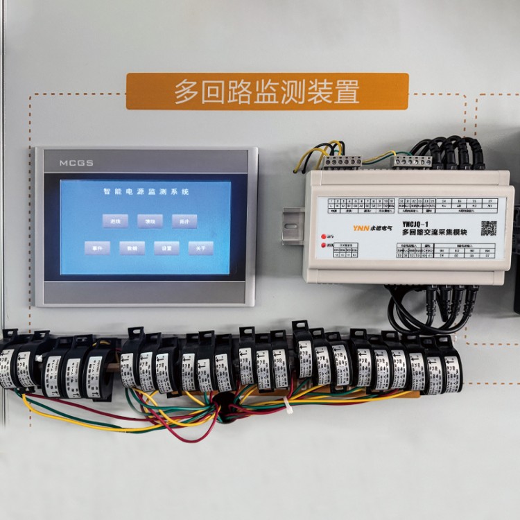
Application Fields: Industrial Manufacturing, Commercial Buildings, Complete Plants, Substations, Public Utilities, etc.
Customization: Offers logo, appearance, and functionality customization services for businesses.
Product Specifications
| Product Name | Accuracy Grade | Rated Voltage | Current Specifications | Pulse Constant |
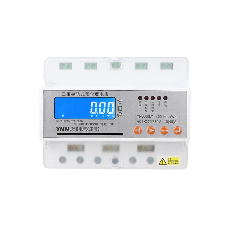
| Track-type Three-Phase Pre-Paid Energy Meter | 1.0 | 3X220/380V | 3X1.5(6)A | 6400imp/kWh |
| 3X5(20)A | 400imp/kWh | |||
| 3X10(40)A | 400imp/kWh | |||
| 3X15(60)A | 400imp/kWh | |||
| 3X20(80)A | 400imp/kWh |
Technical Specifications
| Project | Technical Specifications |
| Power accuracy grade | 1.0 Level |
| Electrical Energy Measurement Range | 0~999999.9KWh |
| Rated Voltage | AC110V AC 220V |
| Current Specifications | 1.5(6)A、5(20)A、10(40)A、20(80)A |
| Working Voltage | Normal: 0.9~1.1 Un; Limit: 0.7~1.2 Un |
| Reference Frequency | 45~65Hz |
| Starting Current | 0.004Ib |
| Power Consumption | ≤5VA |
| Pulse Output | Pulse Width: 80±20ms Optocoupler Isolated Output |
| Digital Communication | RS485 interface, Modbus-RTU protocol, baud rate 9600 bps, no parity |
| Temperature Range | -10℃~+55℃ |
| Relative Humidity | ≤95% No Dew Point |
| Dimensions | 126×94×84 |
Dimensions and wiring diagram
Exterior dimensions

Installation Diagram
The installation is via a 35mm standard rail system, as shown below:

Wiring diagram

Note:
Ensure the screws are tightly tightened during wiring to prevent the instrument from malfunctioning due to poor contact.
2. When the input current exceeds 100A, an external 5A current transformer is required. In this case, the user's opening and closing operations must be performed using an external circuit breaker or contactor.
3. The alarm output is a relay passive dry contact output. When the remaining battery power of the user falls below the second-level alarm power or is 0, the relay closes to output the disconnection signal (relay capacity: AC 250V, 5A).
4. The wiring method for current specifications greater than 100A is shown as follows:


Real-time Monitoring: Voltage, Current, Power, Frequency, Power Factor, Energy
LCD Liquid Crystal Display
Communication: 1-way RS485 communication function, MODBUS-RTU protocol or DLT645-2007 protocol
Installation Method: Rail mounting, enhancing work efficiency
Power Failure Protection: Data is automatically saved and records are not lost after power failure.
Application Fields: Industrial Manufacturing, Commercial Buildings, Complete Plants, Substations, Public Utilities, etc.
Customization: Offers logo, appearance, and functionality customization services for businesses.
Product Specifications
| Product Name | Accuracy Grade | Rated Voltage | Current Specifications | Pulse Constant |
| Track-type Three-Phase Pre-Paid Energy Meter | 1.0 | 3X220/380V | 3X1.5(6)A | 6400imp/kWh |
| 3X5(20)A | 400imp/kWh | |||
| 3X10(40)A | 400imp/kWh | |||
| 3X15(60)A | 400imp/kWh | |||
| 3X20(80)A | 400imp/kWh |
Technical Specifications
| Project | Technical Specifications |
| Power accuracy grade | 1.0 Level |
| Electrical Energy Measurement Range | 0~999999.9KWh |
| Rated Voltage | AC110V AC 220V |
| Current Specifications | 1.5(6)A、5(20)A、10(40)A、20(80)A |
| Working Voltage | Normal: 0.9~1.1 Un; Limit: 0.7~1.2 Un |
| Reference Frequency | 45~65Hz |
| Starting Current | 0.004Ib |
| Power Consumption | ≤5VA |
| Pulse Output | Pulse Width: 80±20ms Optocoupler Isolated Output |
| Digital Communication | RS485 interface, Modbus-RTU protocol, baud rate 9600 bps, no parity |
| Temperature Range | -10℃~+55℃ |
| Relative Humidity | ≤95% No Dew Point |
| Dimensions | 126×94×84 |
Dimensions and wiring diagram
Exterior dimensions
Installation Diagram
The installation is via a 35mm standard rail system, as shown below:
Wiring diagram
Note:
Ensure the screws are tightly tightened during wiring to prevent the instrument from malfunctioning due to poor contact.
2. When the input current exceeds 100A, an external 5A current transformer is required. In this case, the user's opening and closing operations must be performed using an external circuit breaker or contactor.
3. The alarm output is a relay passive dry contact output. When the remaining battery power of the user falls below the second-level alarm power or is 0, the relay closes to output the disconnection signal (relay capacity: AC 250V, 5A).
4. The wiring method for current specifications greater than 100A is shown as follows:
| 品牌: | Yongnuo Electrical |
| Brand: | Yong诺Electric |
| Region: | National |
| Model: | Customizable |
| 单价: | 电议 |
| 最小起订Quantity: | |
| 供货总Quantity: | |
| 有效期至: | 长期有效 |
| 最后更新: | 2025-04-29 13:18 |