


How to identify the authenticity of a Siemens PLC module?
1. Packaging is very similar to the authentic version; just by looking at it, you can't tell the difference. The authentic packaging has a serial number, and you can verify it by entering the serial number into Siemens. Additionally, all Siemens PLC product modules come with a barcode, which you can use to call and check the authenticity of the product by querying the barcode.
2. Examine the assembly or disassemble to see the craftsmanship (distinguish through circuitry diagrams or the production serial numbers on the circuit board); it's recommended to open it up and inspect the PCB board. Original packaging is still noticeable, and the workmanship of a fake Siemens differs from the original, but that doesn't necessarily mean it's of poor quality.
Siemens PLC Module Control System Program Structure Design
Linear Programming
Linear programming involves placing the user program sequentially within a single instruction block, meaning a simple program block contains all system instructions. Linear programming lacks branches, typically executing each instruction in the OB1 program in order, making the software's functionalities relatively straightforward.
Section 2: Modular Programming
Modular programming involves dividing a control task into several independent blocks, each block controlling the logic instructions for a set of equipment or a series of operations, with the execution of these blocks relying on the instructions within the Organizational Block (OB) to call them.
Structured Programming
Structured programming categorizes similar or related process requirements and attempts to provide a universal solution that can be applied to multiple tasks. By providing information to the instruction block (in the form of parameters), structured programs can reuse these universal modules.
Control software is divided into five functional blocks:
FC10 - Function block for controlling the feed pump for Component A
FC20 Function block for controlling the feed pump for Component B.
FC30 Function block for controlling agitators
F0 Function block for controlling the material discharge solenoid valve.
FC50 - Function block for controlling indicator lights on the operator station.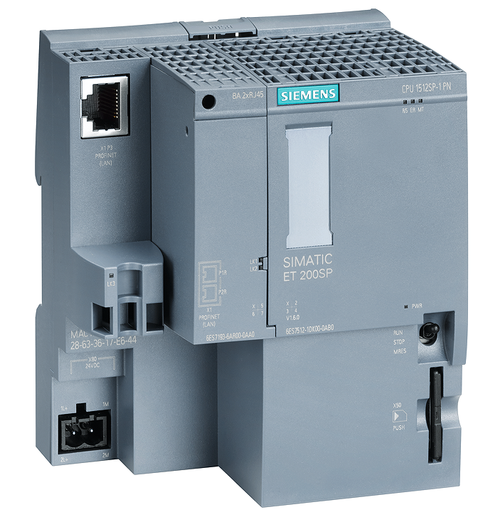 Siemens modules are categorized into switch input/output modules, analog input modules, analog input/output modules, analog output modules, communication modules, and expansion modules, etc. Siemens modules offer sufficient stability to ensure safety during operation. Siemens' own modules employ a series of highly reliable design methods, such as power failure protection and information protection, including fault diagnosis. To better control industrial production processes, computer programming languages are typically used, making the entire control more reliable and straightforward. Moreover, all programming languages have been simplified, significantly reducing the error rate.
Siemens PLC Selection Analysis:
When selecting a Siemens PLC, certain principles should be followed to avoid the scenario where the PLC's capacity is too small to meet the usage requirements. When choosing based on control requirements, opt for the best cost-performance ratio. Generally, consider the following aspects:
I/O Point Estimation
The I/O points are a crucial indicator for Siemens PLCs. Selecting the I/O points appropriately can not only meet the control requirements of the system but also keep the total system investment low. The total number and types of input/output points for Siemens PLCs should be determined based on the controlled object's analog and digital signals, input/output devices (including analog and digital signals, output types), and generally, one input/output element occupies one I/O point. Considering future expansion, it's advisable to estimate a total point count and add an additional 15% to 20% for spares.
I. User Storage Capacity Estimation
The amount of memory used by a user application is influenced by many factors, such as I/O points, control requirements, computational processing volume, and range structures. Therefore, only a rough estimate can be made before program design. Based on experience, the memory usage for each I/O point and related function is roughly as follows:
Switching Input Elements: 10-20B/point
Switching Output Element: 5-10B/point
Timer/Counter: 2B/pc
Analog Quantity: 100~150B/point
Communication Interface: A single interface typically requires over 300B; supports communication with the Weilin MT6100IV5 touch screen.
Based on the total word count calculated above, plus an additional 25% reserve, you can estimate the memory required for the program, thereby selecting the appropriate Siemens PLC memory.
Section II: Calculation of I/O points occupied by this design
Input Signals: Start button requires one input point; Stop button requires one input point; Increment count by 1 button requires one input point; Decrement count by 1 button requires one input point. A total of 4 input signal points are needed. To account for future system adjustments and expansions, an additional 20%备用 points are reserved, which is 4 x 20% = 1 point. Therefore, a total of 5 input points are utilized.
Output Signal: A total of seventeen LED seven-segment displays are required, with 8 output points needed for segment selection codes; if a 74LS138 decoder is used for the bit select signal, 4 output points are required. In total, 13 output points are needed. Considering future adjustments and system expansion, an additional 20% reserve is provided, which is 13 x 20% = 2.6, rounded up to 3 points. Therefore, a total of 16 output points are used.
Basic Content of Siemens PLC Module Control System Design:
1. Determine the system's operational and control methods: PLCs can form various control systems, such as single-machine control systems and centralized control systems. When designing the application system, it is essential to determine the system's composition form.
2. Select user input devices (buttons, operational switches, limit switches, sensors, etc.), output devices (relays, contactors, signal lights, etc.), and controlled objects driven by the output devices (motors, solenoid valves, etc.). These devices are general electrical components, and the methods for selecting them are covered in other courses.
3. PLC Selection: PLC is a core component of the control system, and the correct choice of PLC plays a crucial role in ensuring the technical and economic indicators of the entire control system. PLC selection should include model selection, capacity selection, I/O module selection, and power module selection.
4. Allocate I/O points, draw I/O connection diagrams, and design a console (cabinet) if necessary.
5. Design Control Program: The control program is the software that governs the entire system's operation, a crucial factor for ensuring the system's normal, safe, and reliable performance. Therefore, the program for the control system should be repeatedly debugged until it meets the required standards.
6. Prepare technical documents for the control system, including manuals, electrical schematics, electrical component lists, I/O connection diagrams, I/O allocation tables, and control software.
Siemens CPU Module 6ES7223-3BD30-0B0
