


I. Usage and Brief Introduction
The central drive single-tube sludge pump is primarily used for sludge removal in the secondary sedimentation tank of the peripheral inflow and outflow in the activated sludge process for wastewater treatment. It is a new product successfully developed by our company in recent years, based on the absorption of domestic and international technologies. The product features low energy consumption, easy operation and maintenance, uniform sludge extraction, and high sludge concentration, enhancing the mechanical performance and stability of the equipment.
II. Structure and Working Principle
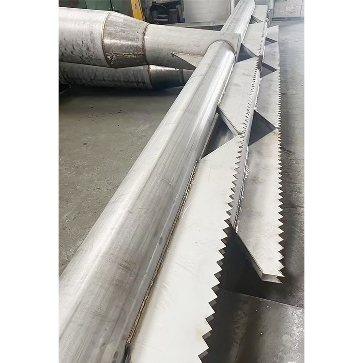
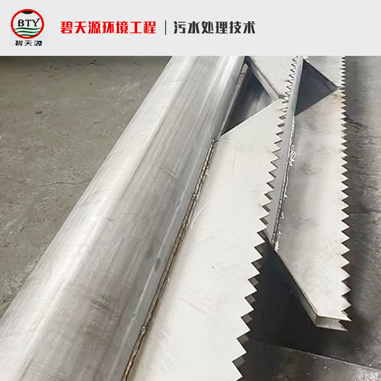
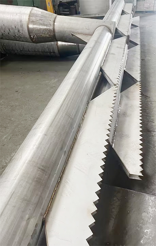
The central drive single-tube sludge suction machine is mainly composed of a central drive unit, central vertical frame, central column, sludge suction pipe, scraper plate, scraper arm, floating sludge scraper assembly, mud collection drum, working bridge, water dam board, and floating sludge hopper, etc.
A sedimentation tank with both inlet and outlet around it is a type of wastewater treatment structure. When the sludge mixture enters the distribution channel, it is evenly distributed throughout the pool through the bottom distribution holes. Under the action of the water-diverting apron, the water flows slowly and evenly from the peripheral pool bottom towards the center in a stratified flow state. Simultaneously, the sludge begins to settle at the pool bottom under gravity, forming a high-concentration primary sludge layer, thus completing the separation of sludge and water. The clarified liquid separated out returns to the upper part and is discharged out of the pool through the surrounding collecting channels. The sludge at the pool bottom is collected through the holes on one side of the sludge suction pipe (aided by the scraper) and discharged into the sludge collection筒. The floating debris on the pool surface is skimmed off by the scraper and discharged out of the pool into the floating debris bucket.
The sludge pump is mounted on the central column of the sedimentation tank and driven by a mechanism to rotate the scraper blade, central upright, scraper arm, mud collection筒 and suction pipe slowly along the bottom of the tank, discharging sludge outside. The amount of sludge discharged is controlled by the opening degree of the sleeve valve inside the sludge outlet well outside the tank. Floating debris on the surface of the tank is撇入the slag hopper by the surface skimming mechanism and discharged outside.
Section 3: Installation and Acceptance of Sludge Pumps
Inspection and acceptance of civil engineering projects:
Suction dredges must be installed after the civil engineering project has passed the acceptance inspection. To ensure a smooth installation, the following points should be checked during the installation process:
The requirement for flatness at the bottom of the pool is ±2mm tolerance.
b. The central pillar is based on the top surface of the swivel support, with a horizontal tolerance of 0.5mm/m.
c. The spherical roller bearing and transmission mechanism should operate smoothly without binding or unusual noises.
d. The skimmer scraper and rake plate are adjusted according to the water level height to a draft depth of 100mm, and the rake plate can pass through the slag hopper smoothly without any jamming.
e. The central upright and mud collection筒 are securely installed; the seal at the bottom of the mud collection筒 should meet design specifications.
f. All bolted connections must be securely fastened; no looseness is permitted.
g. All weld joints at site during installation must comply with the specifications of GB324-88 for their shape and size. All welds must ensure strength and reliability, and any spatter, oxide scale, or slag should be removed. Cracks, inclusion, and burn-through defects are not permitted.
h. The installation checks for the central pillar and the central upright must comply with the requirements of the civil engineering construction drawings. During inspection, the central pillar and the central upright must be perpendicular, and the gaps around them must be equal.
2. Center Pillar Installation
The center pillar must be leveled and aligned before tightening the bolts, then the silt collector and bottom plate are installed first. The bottom plate must be ensured to be flat, followed by the installation of the central transmission vertical frame, the top rotating bearing, and the combination of the rotating bearing with the central vertical frame and the central transmission vertical frame for smooth rotation.
3. Scraper Arm Installation: One end of the scraper arm is bolted to the center drive upright, and is leveled with a tie rod.
4. Suction Tube Installation
The mud pipe is connected to the sump flange at one end, secured to each part with scraper arms, and the flat mud scraper is adjusted to maintain a 50mm gap from the pool bottom. The balance of the two scraper arms is regulated by the counterweights in the weight boxes at both ends of the scraper arms.
5. Drive Assembly Installation: Install the drive assembly under the condition that the scraper arm rotates freely.
6. Workbridge Installation: The workbridge is connected to the drive unit at one end and welded to the pre-buried steel plate on the pool surface at the other, or secured with expansion bolts. Be sure to identify the directions of both ends when installing the workbridge.
7. Scum Rake Blade: Install the scraper bracket on the upper part of the scraper arm, attach the scraper blade, adjust its height, and then tighten the bolt after ensuring it's qualified.
8. Skimming Funnel: Weld the skimming funnel bracket to the embedded steel plate or secure it with expansion bolts. Adjust and tighten its position in conjunction with the skimming baffle.
9. Overflow Plate Skimmer Baffle Installation: Secure the overflow weir plate with expansion bolts to the collecting trough, ensuring the weir plate is level and adjustable in height. Adjust after filling the pool with water to improve the levelness. Install the skimmer baffle after the weir plate is properly set.
10. Inspection and Operation: After all parts of the sludge remover are installed and the bottom surface of the pool is leveled, fill the pool with clean water, adjust the overflow and scum spout, operate the sludge remover continuously for 24-48 hours, and check if the electrical overcurrent protection device is functioning properly (operation is allowed only after these inspections pass).
IV. Usage, Maintenance, and Precautions for Suction Dredges
Use of Mud Sucker
The mud cleaner is installed and upon passing the inspection, it is ready for operation. Before starting the machine, the following steps should be taken:
Fill the pool with clean water to ensure the smooth start-up and operation of the scraper.
b. Activate the start button switch to initiate the machine.
Wastewater can only be discharged after the vehicle operates normally. If there are changes in the treatment process, it must be readjusted. The sludge pump is controlled in the control room. For safe operation, a switch box is installed at the pump end for on-site start-up and shutdown.
2. Maintenance of mud pumps
The mud sucker requires regular maintenance, with a major overhaul inspection annually. During maintenance and inspections, it is essential to consistently:
Ensure the oil level in the reducer is correct and lubricate all moving parts during the operation of the sludge pump.
b. Inspect all water connections on the mud cleaner for looseness.
c. Inspect the seal integrity of the rotating sealing device.
c. During major overhauls, inspect the corrosion on underwater parts, the sealing condition of each sealing element, and the wear on rubber scraper blades, etc.
d. During major overhauls, reapply anti-corrosion coatings as specified in the mud cleaner construction drawings.
3. When operating the mud cleaner, please note:
The machine is equipped with an overcurrent protection device that can automatically stop the machine in case of a fault. A safety shear pin is installed on the drive unit, which can be cut off if it exceeds the allowable limit to ensure motor safety.
b. After parking and rectifying the fault, if restarting is difficult, remove the mud pump's drive chain, push it manually, and then start the motor.
V. Operation Requirements:
1. No garbage or obstructions are to be left in the pool area or walkways.
2. Operation with no load must last for not less than 2 hours, with no interference or abnormal sounds or vibrations from any moving parts. The mud scraper must not come into contact with the higher part of the pool bottom (caused by civil engineering construction).
3. Operation under load should be conducted after the unit has been operated at no load for a period of not less than 24 hours.
4. Upon shutdown, water supply to the pool should be stopped first, and the sludge scraper should continue to operate for 2 weeks before parking.
5. Regularly replenish lubricating grease for the spherical roller bearing, and fill the reducer's lubricant to the level indicated by the oil gauge.
6. Electrical operations according to the electrical wiring diagram
Section 6: Maintenance and Repair
1. Regularly inspect the lubricating oil in the reducer, ensure proper oil level, and replace it periodically. (See reducer manual for details.)
2. Add calcium-based lubricant using a high-pressure gun to the equipment's radial bearings every three months for lubrication.
3. Conduct an annual inspection, replacing worn-out parts promptly, and repaint any areas where paint has chipped off.
Section 7: Main Technical Parameters:
·Equipment Name: Central Drive Single Tube Sludge Sucker
·Number of mud pumps: 2 sets
·Model: ZXX24
· Tank Diameter: φ24m
· Sedimentation Pond Type: Weekly In-Weekly Out Sedimentation Pond
·Periphery line speed: ~3m/min
·Working Medium: Municipal Sewage (Active Sludge Mixture)
·Work Bridge: Semi-girder Fixed Type
· Pool Depth: 4.3m
·Effective water depth by poolside: 4.15m
· Motor Power: 0.37 Kw
Motor Protection Grade: IP55
Motor Insulation Grade: F Class
