


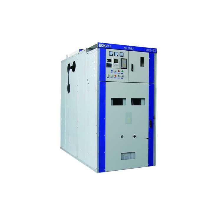
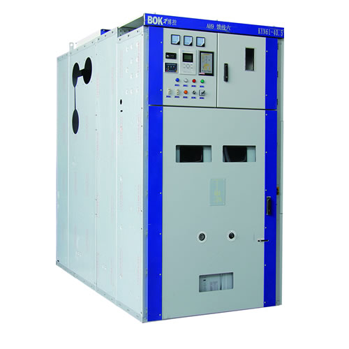
Structure Features of Switchgear Cabinets
Busbar Room
Telecommunications room
The switch cabinets are designed according to the GB3906-1991 and IEC298 standards for armored metal-enclosed switchgear. The whole is composed of
The cabinet and the retractable section (handcart) are composed of two parts. The cabinet structure is assembled, connected by bolts to form a unit.
Metal partition panels divide the interior of the switchgear into the circuit breaker room, main busbar room, cable room, and relay instrument room. Enclosure protection
Grade reaches IP3X, each compartment is IP2X, and all metal structural components are reliably grounded, main circuit system
Each compartment features an independent exhaust pressure relief channel.
1. Shell and separator
The casing and partitions of the switch cabinets are assembled by bolting together cold-rolled steel plates that have been processed and bent on CNC machines. Therefore, the assembly
A good switchgear cabinet ensures uniformity in structural dimensions. The switchgear is divided into the circuit breaker room, main busbar room, cable room, and relay...
Electrical instrument room, all parts are separated by grounded metal partitions.
2. Handcart
Hand carts are categorized by their use into circuit breaker hand carts, voltage stone container hand carts, metering hand carts, and disconnection hand carts, among others. Hand carts of the same type share identical dimensions, and those with the same purpose are interchangeable.
The handcart is equipped with a test/隔离 position and a working position within the cabinet. Each position is fitted with an interlock mechanism to ensure that the handcart cannot be moved freely when it is in either of the two positions.
3. Circuit Breaker Compartment
The circuit breaker compartment is equipped with specific tracks for the handcart to move. As the circuit breaker moves between the test and working positions, the isolation door automatically opens or closes, ensuring the safety of the staff.
Contact with live parts. The switchgear can be operated with the cabinet door closed. The position of the switchgear inside the cabinet and any function indicators on it can be observed through the viewing window.
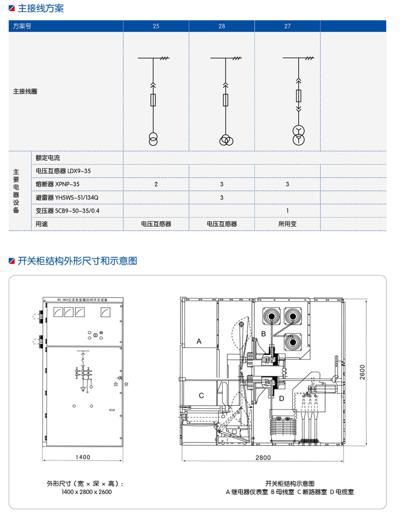
Busway Compartment
The main busbar is routed from one switchgear cabinet to another via branch busbars and fixed with static contact boxes. It is secured with busbar sleeves when crossing the side panel of an adjacent cabinet. All busbars use a composite insulation method.
5. Cable Compartment
Cable tray is suitable for installation of PT grounding switches, lightning arresters, and multiple cables.
6. Relay Room
Releaver room interior panels and panels can be installed with control, protection elements, meters, display instruments, and live monitoring indicators, etc., as secondary components.
7. Interlock device
The switchgear features a reliable interlock mechanism, ensuring the safety of both operators and equipment.