


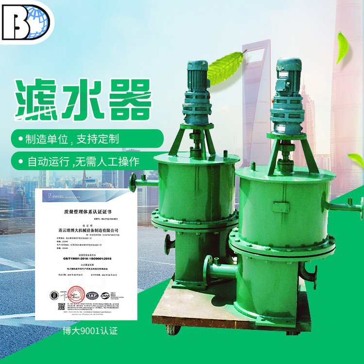

I. Industrial Water Filter Applications
Installed on water supply pipelines in power stations, chemical industry, dyeing and printing, papermaking, and various other industries, mainly suitable for pipelines with a diameter of 500mm or less, and possesses the following advantages:
1: Compact in size, easy for on-site arrangement and installation. Electric water filter, industrial water filter
2: The water filter's inlet and outlet are designed in a split upper-lower structure, which not only prevents direct water pressure impact on the filter mesh but also alters the traditional filter mesh's filtration process where debris is far from the drain outlet. This requires cleaning each filter chamber individually during drainage, often leading to clogging issues.
3: Mesh Material and Structure: Enhances the flow-through area of water, effectively reducing water resistance of the filter mesh, ensuring reliable operation without jamming, clogging, or blocking, significantly extending the lifespan of the filter mesh.
Filter screens are made from a single stamping of 2-8mm stainless steel sheet, with the core able to withstand a differential pressure of 150 kPa without deformation or damage. They feature a long service life, resistance to corrosion, non-corrosion, smooth surface, and non-scaling properties.
5: Electric device operates at a slow speed with smooth running, capable of forward and reverse operation through a differential pressure controller. The timer can automatically start the decelerator for forward and reverse flushing, featuring strong cleaning effect and low water consumption for waste discharge.
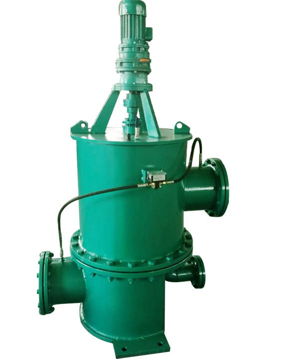
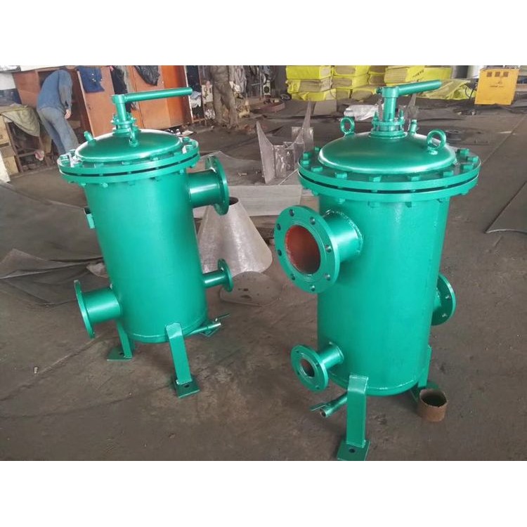
II. Structure
Filter systems are available in manual and electric models, mainly consisting of:
1. Rotating shaft assembly 2. Inlet and outlet water ports 3. Bracket housing 4. Mesh core system 5. Electric reducer (including electrical cabinet) 6. Drainage outlets, etc., constitute. Water filter, industrial water filter, pipeline filter
Section 3: Operating Principle
Manual Process: After the filter is connected to the pipeline system, water enters the filter through the lower inlet. As impurities in the water pass through the core mesh, those with a larger volume than the mesh holes are trapped on the mesh. Once accumulated to a certain amount, a pressure difference is created between the inlet and outlet. (The pressure difference varies with the mesh precision diameter, typically around 0.15 Mpa.) Manually open the drain valve to start draining. Rotate the handle in either clockwise or counterclockwise direction, turning one step every 10 to 30 seconds. The handle is fixed at each indentation. The water reverses to flush the impurities and dirt adhering to the inner wall surface of the core mesh. Continue until a full rotation is completed, then close the drain valve to finish manual draining.
If the user selects an automatic water filter, options include differential pressure drainage and timed drainage.
1. Differential Pressure Backflushing: Once impurities accumulate to a certain quantity, utilize the differential pressure signal between the cooling water inlet and outlet pipes for backflushing. This involves the electrical contact pressure gauge sending a control signal, which then activates the control mechanism to open the electric backflush valve. The electric reducer operates at a speed of 3-6 rotations per minute, reversing the flow of water to flush away impurities adhering to the inner wall surface of the mesh core. The flushed-out debris is then discharged into the cooling water outlet pipe through the backflushing pipeline and valve.
2. Users can set the effluent timing as needed, from 0 to 9999 hours, to determine the cleaning and effluent time. Generally, effluent is set to occur every 12 hours, and the timing can be adjusted according to the water quality of the power plant. Reverse the electric reducer to open the effluent valve, and then proceed with reverse flushing and effluent discharge in sequence.