


详情描述
Hydrogen Energy Sandtable Model Scenario Full Analysis: Hydrogen Production, Storage, Transportation, and Utilization
One,
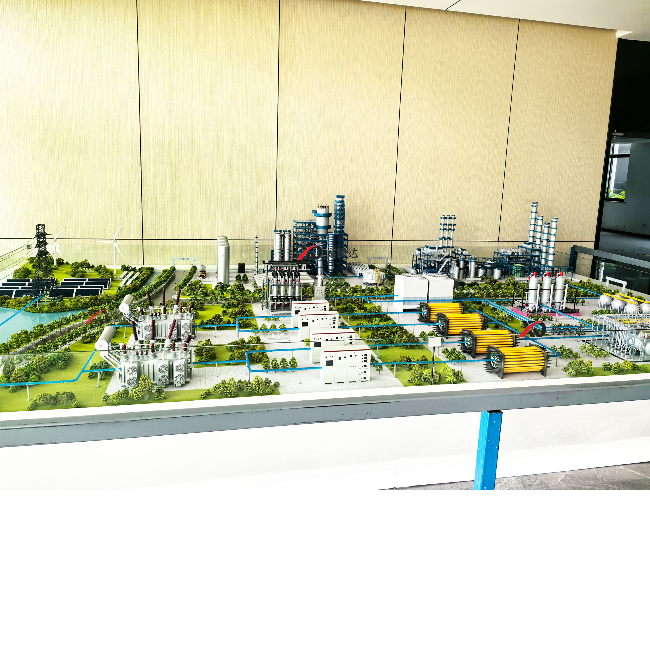
Hydrogen energy, as a highly promising clean energy solution for the future, is gradually gaining public attention. To provide the public with a more intuitive and in-depth understanding of the entire process from production to application of hydrogen energy, the Shanghai Xinfengda Model Co., Ltd. has developed a hydrogen energy science popularization sandbox model. Through clever design and presentation, it vividly showcases the three core processes of hydrogen production, storage, and transportation, and utilization, making it a powerful tool for popularizing hydrogen energy knowledge. Next, we will delve into the details of this hydrogen energy sandbox scenario.
II. Hydrogen Production Phase
(1) Electrolytic Water Hydrogen Production
Display Area
At the prominent location on the sand table, the electrolysis water hydrogen production area is the key display content. Here, the process of splitting water into H2 and oxygen using electrical energy is presented through exquisite models and multimedia displays.
The model's main body is a transparent electrolytic cell, with electrode plates neatly arranged inside. The electrode plates are made of special materials to simulate, as described by the adjacent signage, typically choosing metal alloys with excellent conductivity and corrosion resistance to ensure electrolytic efficiency and the longevity of the device. Through the transparent shell, the simulated electrolyte can be seen slowly flowing between the electrode plates. After the power is connected, the lights flicker to simulate the passage of current, and the water molecules undergo amazing transformations on the electrode surface. In the cathode area, hydrogen ions gain electrons to form H2, with tiny bubble models continuously erupting; in the anode area, oxygen is produced, also displayed as bubble models.
Shanghai Xinfengda Models has set up multiple comparison display units on the sand table to showcase different types of electrolytic water technology. Adjacent to the alkaline electrolytic cell model, a detailed description of its working principle is provided:KOHAlkaline solutions are used as the electrolyte, with relatively low cost for electrode materials, mature technology, and were the primary method for early electrolytic water hydrogen production. An adjacent electronic screen displays an animation illustrating the movement and reaction of ions in the alkaline electrolyte.
Proton Exchange Membrane
The (PEM) electrolyzer model showcases its compact structure. The markings on the model indicate that the PEM electrolyzer uses a proton exchange membrane as a key component, which efficiently conducts protons and separates gases. This electrolyzer responds quickly, has high current density, and is suitable for pairing with renewable energy sources due to the intermittent nature of renewable energy generation, as the PEM electrolyzer can rapidly adapt to changes in power input. The animation on the screen demonstrates the proton conduction path within the membrane and the generation process of H2 and oxygen.
Solid Oxide Electrolyzer Cells
The (SOEC) model showcases its characteristics of operation in high-temperature environments. High-temperature conditions enhance electrolysis efficiency and enable the cascaded utilization of waste heat. The description next to the model explains the potential advantages of SOEC in future large-scale energy storage and hydrogen production integration projects, with animations illustrating the ion conduction and chemical reaction processes under high temperatures.
The control center model is a crucial component of the electrolysis water-to-hydrogen demonstration. The console is brimming with various buttons, dials, and screens, simulating real-time monitoring and precise control of the electrolysis process. Visitors can adjust parameters such as current strength, voltage, and electrolyte flow through interactive screens, observing the changes in the electrolysis reaction within the model.
(H) Hydrogen Production from Fossil Fuel Reforming
Display Area
Adjacent to the electrolytic water hydrogen production area, the fossil fuel reforming hydrogen production zone demonstrates another common hydrogen production method. For example, with natural gas reforming, a sand table model has been constructed to depict the entire process.
Firstly, the natural/gas pretreatment unit model catches the eye, simulating the process of removing impurities from natural/gas, such as H2S and carbon dioxide. The pretreated natural/gas is mixed with steam and then enters the reformer model. The reformer is filled with simulated nickel-based catalysts, and the lights on the furnace simulate a high-temperature environment (typically 700-1000°C). In this area, an animation and voice explanation introduce the reforming reaction that occurs between natural/gas and steam under the action of the catalyst: CH₄ + H₂O ⇌ CO + 3H₂.
The mixed gas produced by the reaction enters the model of the conversion reaction unit. Here, CO reacts further with water vapor to produce carbon dioxide and more H2: CO + H₂O ⇌ CO₂ + H₂. The model simulates the transmission and reaction process of gases through pipes and balls of different colors, allowing visitors to clearly see the transformation of matter.
Next, the mixed gas enters the purification processing area, where a series of adsorption towers and filter models demonstrate the decarbonization and desulfurization processes. Through textual descriptions and animated demonstrations, visitors learn how these processes remove impurities such as carbon dioxide and sulfur compounds, ultimately yielding high-purity H2. The entire fossil fuel reforming hydrogen production area provides a comprehensive understanding through models, animations, and explanations, covering the process flow, chemical reaction principles, and key operational points of this hydrogen production method.
(Bio) Hydrogen Production
Display Area
The Biohydrogen area presents visitors with a green and environmentally friendly hydrogen production method, divided into two parts: photo-biological hydrogen production and fermentation-based biohydrogen production.
The photosynthetic hydrogen production section is centered around a transparent culture tank model, simulating the growth environment of algae or cyanobacteria. The tank is equipped with a lighting system outside to mimic sunlight. Through the transparent tank walls, you can observe the small biological models actively growing under the light. An adjacent electronic screen displays an animation of the process where microorganisms utilize light energy to split water into H2 and oxygen at the microscopic level. The text description introduces factors affecting photosynthetic hydrogen production, such as light intensity, temperature, and pH level.
The anaerobic hydrogen production area showcases a fermentation tank model, filled with simulated carbohydrate-rich organic materials such as straw and manure. The model simulates the fermentation process of anaerobic bacteria on organic matter in an oxygen-free environment through flickering lights and liquid flow in the pipes. Under appropriate temperature and pH conditions, the anaerobic bacteria decompose the organic matter into products such as H2, carbon dioxide, and organic acids. The gas produced by fermentation is connected to a model of a gas collection and separation unit through pipes, and after a series of treatments, pure H2 is obtained. This area highlights the renewable resource utilization, environmental friendliness, and the potential application prospects in the agricultural and waste treatment fields of bio-hydrogen production.
Section 3: Hydrogen Storage and Transportation
High-pressure gaseous hydrogen storage
Display Area
The high-pressure gaseous hydrogen storage area in the hydrogen storage process showcases the storage method of H2 under high pressure. The model of various high-pressure hydrogen storage containers of different specifications is displayed on the sand table, ranging from车载 hydrogen storage cylinders for small-scale applications to fixed hydrogen storage tanks for large industrial sites.
Hydrogen storage containers are made of transparent or semi-transparent materials for easy observation of their internal structure by visitors. The interior simulates a high-strength alloy steel or composite material construction, and the adjacent informational plaque explains how these materials can withstand pressures up to several tens or even hundreds of megapascals.
On one side of the display area, a compressor model is set up, simulating the process of H2 being compressed and filled into a hydrogen storage container under the action of the compressor through mechanical movement. The model of the compressor's piston or rotating impeller moves rhythmically, accompanied by lighting and sound effects, immersing visitors in the experience.
Hydrogen storage containers are equipped with various simulated safety devices, such as pressure sensors and safety valves. The safety valve models simulate the opening and pressure release process when the pressure is too high, alerting visitors to safety concerns with audio-visual effects.
The pipeline system model connected to the hydrogen storage container demonstrates the distribution and transportation paths of H2. Different colored pipes represent H2 transportation lines of varying pressure levels, with valve models on the pipes that can be manually operated to simulate the control of H2 flow and volume. Through this interactive display, visitors can understand how H2 is transported from storage points to different application scenarios, such as hydrogen refueling stations and factories.
(Low Temperature Liquid Hydrogen Storage)
Display Area
The Low Temperature Liquid Hydrogen Storage area showcases the technology of cooling H2 to a low temperature to become liquid for storage. A large-scale model of a low temperature hydrogen storage tank occupies the central position of the area, featuring a double-layer vacuum insulation structure simulation. The outer tank protects the inner tank, reducing the heat transfer.
The refrigeration system model is a crucial component in the display of low-temperature liquid hydrogen storage. A series of pipeline, compressor, and cooler models showcase the complex process of H2 liquefaction. The refrigeration system utilizes refrigerants (such as helium, nitrogen, etc.), gradually cooling H2 below -253℃ through multi-stage compression and refrigeration cycles, transforming it into a liquid state. The model's lighting and flowing liquid simulation mimic the state changes and energy transfer during the refrigeration process.
On the hydrogen storage tank, multiple simulated monitoring devices have been modeled, labeled with parameters indicating the tank's internal temperature, liquid level, and pressure. Due to the inevitable evaporation of liquid hydrogen during storage, the evaporated H2 is processed through a recovery system model. The recovery system demonstrates how the evaporated H2 is recompressed and cooled, allowing it to return to storage or be used for other purposes.
Hydrogen transmission pipelines are simulated using colored transparent materials, connected to remote application scenario models such as large-scale hydrogen power stations or aerospace bases. This showcases the advantages of low-temperature liquid hydrogen storage in long-distance, large-capacity hydrogen transmission, as well as its application potential in specific fields.
Solid-State Hydrogen Storage
Display Area
The solid-state hydrogen storage area showcases innovative technologies using solid materials like metal hydrides or organic liquids to store H2. Displayed on the model sand table are samples of various types of solid-state hydrogen storage materials, accompanied by detailed textual descriptions explaining their chemical composition, storage principles, and performance characteristics.
For metal hydride hydrogen storage, a hydrogen storage container model is internally filled with simulated metal alloy materials, such as magnesium-based, titanium-iron-based, and other metal hydrides. Through animated demonstrations and physical interactions, visitors can understand how H2 reacts chemically with metal alloys under certain temperatures and pressures to form metal hydrides and store H2.
The Organic Liquid Hydrogen Storage section showcases special organic compound models, such as benzene and C₇H₈. Under the action of catalysts, these organic compounds undergo hydrogenation reactions with H2, storing H2 within their molecular structures. The model demonstrates the hydrogenation and dehydrogenation processes with lights, highlighting the high hydrogen storage density and mild storage conditions of organic liquids, as well as their potential application prospects in mobile hydrogen storage and distributed energy systems.
(4) Hydrogen Pipeline and Transportation Vehicle Display Area
The hydrogen pipeline display showcases a vast and intricate model of a pipeline network, covering a significant portion of the sand table. The pipeline model utilizes different colors and thicknesses to distinguish various pressure levels and purposes of the hydrogen transportation lines, with various valve and booster station models scattered along the pipes.
Valve models can be manually operated to simulate the direction and flow rate of H2. The booster station model demonstrates how to replenish pressure during H2 transportation, ensuring stable and long-distance delivery of H2 to various user endpoints.
The transportation vehicle display area showcases various types of H2 transportation vehicle models, including gaseous hydrogen transport trucks and liquid hydrogen transport tankers. The gaseous hydrogen transport truck model is equipped with multiple high-pressure hydrogen storage cylinders, connecting to hydrogen storage facilities and user ends via a model of specialized loading and unloading equipment, demonstrating its flexibility in short-haul, small-lot H2 transportation.
The liquid hydrogen transport tank truck model features a larger tank, simulating advanced insulation technology to minimize evaporation losses during transportation. The model of the loading and unloading equipment for the tank trucks demonstrates connection methods with various storage and usage locations, highlighting the advantages of liquid hydrogen in long-distance, large-capacity transportation. These transport vehicle models, in conjunction with the hydrogen transmission pipeline models, showcase diverse transportation methods for H2 over different distances and application scenarios.
IV. Hydrogen Processing Phase
Hydrogen Showcase for Transportation Sector
- Hydrogen Fuel Cell Vehicles
- The exhibit area in the transportation sector is a key application scenario for hydrogen energy, with the hydrogen fuel cell vehicle display area being one of the focal points of the sand table. Here, various models of hydrogen fuel cell vehicles are showcased, covering different types such as sedans, buses, and logistics vehicles.
Each car model is dissected in detail, allowing visitors to clearly see the layout of the internal key components. The hydrogen fuel cell stack model is located at the vehicle's bottom or engine compartment, with its internal structure displayed through a transparent casing. The fuel cell stack is composed of multiple single batteries connected in series, with the anode, cathode, and electrolyte membrane of each single battery clearly visible. An adjacent electronic screen plays an animation, demonstrating the process of H2 being decomposed into hydrogen ions and electrons by the anode catalyst, the electrons forming a current through the external circuit to drive the motor, and the hydrogen ions migrating through the electrolyte membrane to the cathode where they combine with oxygen to form water.
The hydrogen storage system model displays the installation location and connection methods of high-pressure gas storage cylinders or low-temperature liquid storage tanks on vehicles. The refueling process is simulated through an interactive device, allowing visitors to operate buttons and observe the demonstration of H2 being quickly and safely refilled into the vehicle's hydrogen storage system from the storage facilities at a hydrogen station.
Hydrogen Fuel Cell Vessels
Adjacent to the hydrogen fuel cell vehicle exhibit area, the hydrogen fuel cell ship exhibit showcases the application of hydrogen energy in water transportation. Models of various types of vessels, including inland river boats, ferries, and small cargo ships, are displayed, all powered by hydrogen fuel cells.
The ship's fuel cell system model demonstrates its similarities to automotive fuel cell systems and its unique design. Due to the larger space on ships, the hydrogen storage system typically employs larger capacity storage tanks, and the model shows their arrangement inside the ship's cabin. The connection between the fuel cell power module and the propulsion system is clearly presented through the transparent hull structure. During the ship's voyage, the model simulates this process through lighting and mechanical movement, illustrating how the electrical power generated by the fuel cell drives the electric motor, which in turn rotates the propeller, propelling the ship forward.
- Hydrogen Fuel Cell Aircraft
- Hydrogen Fuel Cell Aircraft Display Area: The氢fuelcellaircraftdisplayarea showcases cutting-edge exploration of hydrogen energy in the aviation field. Given the strict requirements of aviation for high energy density and safety, the development of hydrogen fuel cell aircraft faces numerous challenges, but also holds immense potential.
The hydrogen fuel cell aircraft concept model displayed on the sand table highlights its unique design features. The wings or fuselage of the aircraft are equipped with simulated hydrogen storage systems and fuel cell power generation modules. Through animated demonstrations, visitors can understand the process of hydrogen reacting in the fuel cells to produce electricity, powering the aircraft's electric propulsion system. Compared to traditional fuel-powered aircraft, hydrogen fuel cell aircraft offer advantages such as zero carbon emissions and low noise. Although most hydrogen fuel cell aircraft are currently in the experimental stage, this exhibit area allows visitors to envision the significant role and vast prospects of hydrogen energy in the sustainable development of the aviation industry in the future.
Part II: Hydrogen Display for Industrial Applications
- Hydrogen Zone for Iron and Steel Metallurgy
- The industrial sector is a significant direction for hydrogen energy applications. The hydrogen zone for iron and steel metallurgy showcases innovative uses of hydrogen in the steel production process, addressing the issue of high carbon emissions in traditional steel production.
The sand table model illustrates a simplified process of iron smelting in a hydrogen-based vertical furnace. After pretreatment, iron ore is fed into the hydrogen-based vertical furnace model. The furnace simulates a high-temperature environment and the reaction between H2 and iron ore. Animated and lighting effects demonstrate the reduction reaction of iron oxide in the iron ore with H2, converting it into metallic iron while water is produced. The informational sign beside the model details the chemical reaction equation and reaction conditions.
The H2 supply system model demonstrates the hydrogen transmission pipelines from the hydrogen production plant to the steel mill, as well as the hydrogen storage facilities and distribution pipelines within the steel mill. The exhaust treatment and H2 recovery process are also illustrated through the model and animation. After treatment of the off-gases generated during the iron-making process, the unreacted H2 is recovered and reused, highlighting the significant role of hydrogen metallurgy technology in achieving green and low-carbon development in the steel industry.
- Hydrogen Zone for Chemical Synthesis
- The Hydrogen Zone for Chemical Synthesis showcases the extensive application of hydrogen in the chemical industry, highlighting two key processes: ammonia synthesis and methanol synthesis.
In the synthesis ammonia section, the sand table model showcases the preparation and purification of raw gases (H2 and nitrogen), followed by the synthetic tower model. Inside the synthetic tower, simulated catalysts are filled. Through lighting and animation demonstrations, the process of H2 and nitrogen reacting under high temperature (about 400-500℃), high pressure (about 15-30MPa), and the action of the catalyst to produce ammonia is illustrated: N₂ + 3H₂ ⇌ 2NH₃. The produced NH3 is then cooled and separated through the model of separation equipment, resulting in ammonia product. Unreacted H2 and nitrogen are returned through the recycle pipeline to the synthetic tower for further reaction.
The Methanol Synthesis Area demonstrates the process of synthesis gas (a mixture of CO and H₂) produced from natural gas or coal entering the synthetic reactor model. Under the action of catalysts, the synthesis gas reacts to produce methanol: CO + 2H₂ ⇌ CH₃OH. The model simulates the transmission and reaction process of substances through pipes and small spheres of different colors, accompanied by text explanations and animation demonstrations, allowing visitors to understand the critical role of H₂ in chemical synthesis and the close connection between the chemical industry and hydrogen energy.
(Distributed Energy and Energy Storage with Hydrogen Display)
- Hydrogen Zone for Distributed Energy The Hydrogen Zone showcases application models of hydrogen energy in distributed energy systems, using a sandbox model of a small community or industrial park as the carrier.
The model features distributed energy equipment such as solar photovoltaic power stations, wind farms, and hydrogen fuel cell generators. During sunny days or when there is wind, the solar photovoltaic power stations and wind farms produce electricity, with excess electricity converted into H2 through a water electrolysis model for storage. The hydrogen storage facility model showcases various storage methods, including high-pressure gaseous storage and solid-state storage.
During peak electricity usage or insufficient renewable energy generation, hydrogen stored in the hydrogen storage facility is converted back into electricity by a hydrogen fuel cell power generation unit, powering the electrical equipment in the community or park. The intelligent control system model displays on an electronic screen how to monitor and adjust the operation of various energy equipment in real-time, achieving the interconversion and storage of electricity and hydrogen energy, as well as the optimized allocation and efficient utilization of energy.
- Energy Storage Hydrogen Zone – The Energy Storage Hydrogen Zone highlights the application scenarios of hydrogen as a large-scale energy storage medium to address the energy storage challenges brought by the large-scale development of renewable energy.
A sand table model was constructed for a large-scale hydrogen energy storage power station, including electrolysis water hydrogen production equipment, hydrogen storage facilities, and fuel cell power generation units. When there is an excess of renewable energy power generation, the electrolysis unit decomposes a large amount of water into H2 and oxygen, with the H2 being stored in large-scale hydrogen storage facilities. When the power grid requires peak load adjustment or backup power, the H2 stored in the facilities is converted into electricity by the fuel cell power generation units and integrated into the grid.
The model demonstrates the energy conversion and flow throughout the entire energy storage process with lighting, animation, and electronic screens. It also showcases the connection and interaction between the hydrogen energy storage power station and the power grid, along with the relevant monitoring and management systems, allowing visitors to understand the significant role of hydrogen energy storage in balancing electricity supply and demand and improving grid stability.
V. Summary
The Hydrogen Energy Knowledge Sand Table Model, through careful design and presentation of the three key links of hydrogen production, storage, transportation, and usage, visually and vividly demonstrates the full picture of the hydrogen energy industry chain to the public. Although it lacks the functions of actual equipment, it effectively stimulates public interest in hydrogen energy and deepens understanding of hydrogen energy technology, playing a positive role in promoting the popularization and development of hydrogen energy.
Xinfengda Models provides an integrated design and manufacturing service for educational simulation training and corporate product exhibitions, covering everything from design, manufacturing, installation, and debugging to product delivery. Our developed products include teaching demonstration models, training simulation devices, science museum educational exhibits, and corporate product display models, serving thousands of schools and enterprises across the country with high-quality products and services.
For more information on hydrogen energy sand table models and training simulation devices, please call for inquiries!


