
Silicon-Controlled Rectifier Overview
Silicon-controlled rectifier, or SCR, is an abbreviation for a type of four-layer, high-power semiconductor device with three PN junctions, typically composed of two thyristors connected in reverse. Its functions include rectification, serving as a rapid on-off switch for contactless switches, inverting DC to AC, and converting AC of one frequency to another, among others. Like other semiconductor devices, the SCR boasts small size, high efficiency, good stability, and reliable operation. Its introduction has enabled semiconductor technology to enter the field of strong electric power, becoming a preferred component in industries ranging from industrial and agricultural to transportation, scientific research, and even commercial and household appliances. Currently, the SCR is widely used in automatic control, mechanical and electrical applications, industrial electrical systems, and household appliances.
Silicon controlled rectifiers are mainly differentiated in shape into three types: spiral, flat, and bottomed. The spiral type is most widely used.
Silicon Controlled Rectifier (SCR) Components
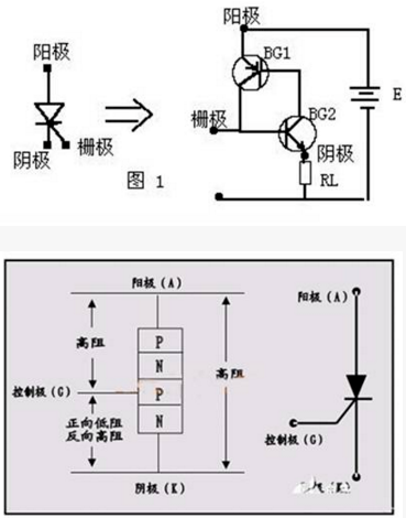
Silicon-controlled rectifiers (SCRs) have three terminals—anode (A), cathode (C), and control terminal (G). The core consists of a four-layer structure made up of alternating P-type and N-type conductors, with a total of three PN junctions, structurally distinct from the silicon rectifier diode, which has only one PN junction. The four-layer structure of the SCR and the introduction of the control terminal lay the foundation for its excellent "small control of large" control characteristics. When an SCR is in use, a very small current or voltage is applied to the control terminal to control a much larger anode current or voltage. Today, SCR devices with current capacities ranging from hundreds to thousands of amperes can be manufactured. SCRs with a current rating below 5 amperes are generally referred to as low-power SCRs, while those above 50 amperes are called high-power SCRs.
Silicon Controlled Rectifier (SCR) Working Principle
We can observe that the second and third layers, counted from the cathode, form an NPN transistor, while the second, third, and fourth layers together form a PNP transistor. The second and third layers are shared by both transistors. An equivalent circuit diagram, as shown in Figure 1, can be drawn. When a forward voltage E is applied between the anode and cathode, and a positive trigger signal is input between the control electrode G and the cathode C (equivalent to the base-emitter of BG2), BG2 generates a base current Ib2, which is amplified, resulting in a collector current IC2 amplified by a factor of β2. Since the collector of BG2 is connected to the base of BG1, IC2 becomes the base current Ib1 for BG1. BG1 then amplifies Ib1 (Ib2) to a collector current IC1, which is fed back to the base of BG2 for further amplification. This cycle of amplification continues until BG1 and BG2 can conduct. In fact, this process is "one trigger and done," as for a silicon-controlled rectifier, once the trigger signal is applied to the control electrode, the SCR conducts immediately. The duration of conduction is mainly determined by the performance of the SCR.
Once triggered, the thyristor remains conductive due to the cyclic feedback, and the current flowing into the base of BG2 is no longer just the initial Ib2, but the amplified current (β1*β2*Ib2) after passing through BG1 and BG2. This current is significantly greater than Ib2, sufficient to maintain the continuous conduction of BG2. At this point, even if the trigger signal disappears, the thyristor remains conductive. It can only be turned off by disconnecting the power supply E or reducing the output voltage of E to a level where the collector currents of BG1 and BG2 are less than the minimum required to maintain conduction. Of course, if the polarity of E is reversed, BG1 and BG2 will be subjected to reverse voltage and will be in the cutoff state. In this case, even with the input trigger signal, the thyristor will not operate. Conversely, if E is connected in the positive polarity while the trigger signal is negative, the thyristor will also not conduct. Additionally, if no trigger signal is applied and the forward anode voltage is sufficiently high to exceed a certain threshold, the thyristor will conduct, but this would be an abnormal operating condition.
Silicon-controlled rectifiers, which control conduction (through large currents in the SCR) by triggering signals (small trigger currents), are distinguished from standard silicon rectifier diodes by this controllable characteristic.
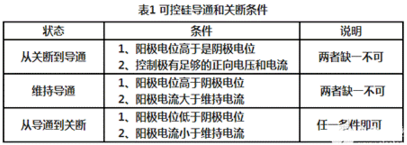
Due to the thyristor's only having two operating states, conductive and off, it possesses switching characteristics that require specific conditions for conversion, as detailed in Table 1.
Principle of Operation for Silicon Controlled Rectifier
Application Examples:
Silicon-controlled rectifiers (SCRs) are widely used in various circuit configurations, with the gate trigger circuit being particularly diverse. This includes DC trigger circuits, AC trigger circuits, phase trigger circuits, and more.
Direct-Current Trigger Circuit
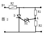
Figure 2 depicts a common over-voltage protection circuit used in televisions. When the E voltage is too high, the voltage at point A also increases. Once it exceeds the voltage regulation value of the voltage regulator DZ, DZ conducts, triggering the thyristor D to conduct, which short-circuits E. This action causes the fuse RJ to melt, thereby providing over-voltage protection.
2. Phase Trigger Circuit:
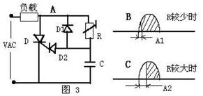
Phase trigger circuits are actually a type of AC trigger circuit, as shown in Figure 3. The method of this circuit is to control the phase of the trigger signal using an RC circuit. When the resistance (R) value is low, the RC time constant is small, resulting in a lesser phase shift (A1) of the trigger signal, thus the load receives a higher electrical power. Conversely, when the resistance (R) value is high, the RC time constant is large, leading to a greater phase shift (A2) of the trigger signal, which reduces the electrical power received by the load. This typical circuit for variable electrical power adjustment is widely used in many electrical products in daily life.
Key parameters of Silicon Controlled Rectifiers include:
Rated Average Current in Conducting State
Under certain conditions, the average of the 50 Hz sine half-wave current that can continuously pass through the anode-cathode is achievable.
2. Positive blocking peak voltage
In the case of a controlled silicon with the open circuit not triggered and the anode positive voltage not exceeding the conduction voltage, the positive peak voltage can be repeatedly applied across the two ends of the silicon. The peak positive voltage the controlled silicon can withstand must not exceed the parameter value provided in the manual.
3. Reverse Breakdown Peak Voltage
When the silicon-controlled rectifier is under reverse voltage and in the reverse-off state, the reverse peak voltage can be repeatedly applied across its terminals. During operation, this parameter value provided in the manual must not be exceeded.
4. Ultra-Touch Current Control
The small control current and voltage required to switch a silicon-controlled rectifier (SCR) from the off state to the conducting state, under specified ambient temperatures, when a certain voltage is applied between the anode and cathode.
Maintain current
At specified temperatures, control the circuit breaker to maintain the small anode forward current required for the thyristor to conduct.
Utilizing可控硅technology for controlling lighting systems offers advantages such as rapid voltage regulation, high precision, the ability to adjust in real-time by time periods, voltage stabilization, and the use of electronic components which are relatively compact, lightweight, and cost-effective. However, this voltage regulation method has a fatal flaw; due to chopping, it cannot achieve sine wave output and generates a significant amount of harmonics, leading to harmonic pollution in the power grid system, posing great harm. It is not suitable for use in circuits with capacitive compensation. (Modern lighting design requirements stipulate that the power factor in lighting systems must reach 0.9 or above, while the power factor of gas discharge lamps is generally below 0.5, necessitating the design of capacitive compensation to improve the power factor.) In developed countries abroad, there are clear regulations regarding the limitation of harmonic content in electrical equipment. In China, major cities such as Beijing, Shanghai, and Guangzhou have restricted the use of equipment with excessive harmonic content in the power grid.
When using silicon-controlled rectifier technology for illuminance control in lighting systems, harmonic pollution can be effectively reduced by adding filter equipment.
In recent years, numerous new thyristor components have been introduced, including rapid thyristors suitable for high-frequency applications, bidirectional thyristors that can be controlled by positive or negative triggering signals to conduct in both directions, and thyristors that can be turned on with a positive triggering signal and off with a negative signal, among others.
Application Introduction——The Application of Silicon Controlled Rectifiers in Dimmers
Silicon-controlled rectifier dimmers are the mainstream equipment in the stage lighting and environmental lighting fields.
Dimmers used in lighting systems are essentially AC voltage regulators. The dimming of old transformers and rheostats was achieved by adjusting the voltage or current amplitude, as shown in the diagram below. u1 represents the waveform of the unregulated 220V AC power, while u2 is the waveform after regulation. Since the amplitude of u2 is less than u1, the light becomes dimmer. In this dimming mode, although the amplitude of the sine AC wave is altered, the fundamental sine waveform remains unchanged.
Compared to transformers and resistors, silicon-controlled rectifiers (SCRs) utilize a different dimming mechanism, employing phase control to achieve voltage or light adjustment. For a standard reverse-blocking SCR, its gate characteristic is such that when a forward anode voltage is applied simultaneously with an appropriate forward control voltage, the SCR conducts; this conduction persists even after the gate control voltage is removed, until a reverse anode voltage is applied or the anode current falls below the SCR's holding current. Standard SCR dimmers leverage this characteristic to achieve leading-edge triggering phase-controlled voltage regulation. At a specific moment t1 (or phase angle wt1) after the sine wave AC voltage passes through zero, a triggering pulse is applied to the SCR control terminal, causing it to conduct. Based on the previously described SCR switching characteristics, this conduction will continue until the positive half-cycle of the sine wave ends. Therefore, within the positive half-cycle of the sine wave (i.e., the 0 to p interval), the SCR does not conduct from 0 to wt1, which is known as the control angle, often denoted as α; while from wt1 to p, the SCR conducts, referred to as the conduction angle, often denoted as j. Similarly, in the negative half-cycle of the sine wave AC, a triggering pulse is applied to another SCR (in the case of two unidirectional SCRs connected in anti-parallel or a bidirectional SCR) at t2 (or phase angle wt2), causing it to conduct. This process repeats, controlling the conduction of the sine wave for each half-cycle, resulting in the same conduction angle. By altering the timing (or phase) of the triggering pulse, the conduction angle j (or control angle α) is changed. A larger conduction angle results in higher output voltage from the dimmer, making the light brighter. From the above SCR dimming principle, it is evident that the output voltage waveform of the dimmer is no longer a sine wave, unless the dimmer is in full conduction state, i.e., the conduction angle is 180° (or π). It is due to the cutting of the sine wave and the distortion of the waveform that interference issues may arise in the power grid...
Proper dimming equipment should take measures to minimize interference generated by the use of可控硅 technology.
