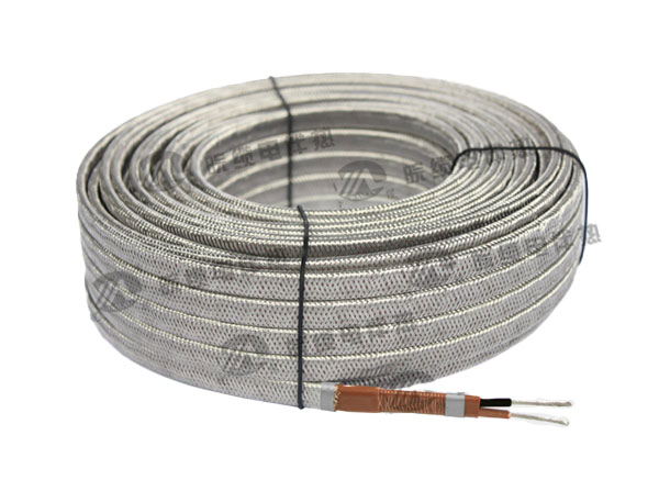


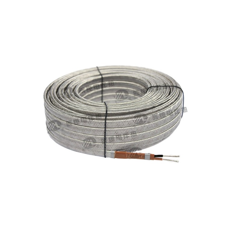
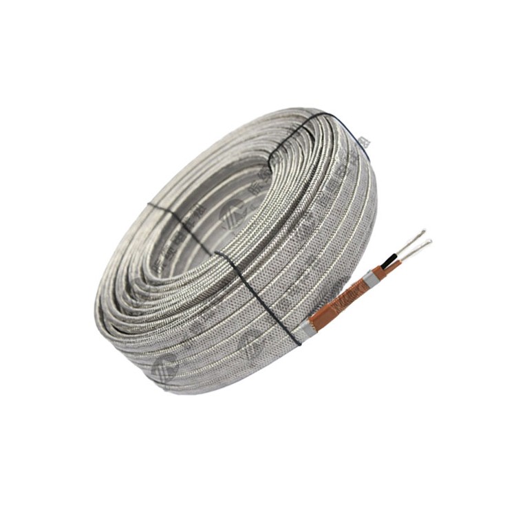
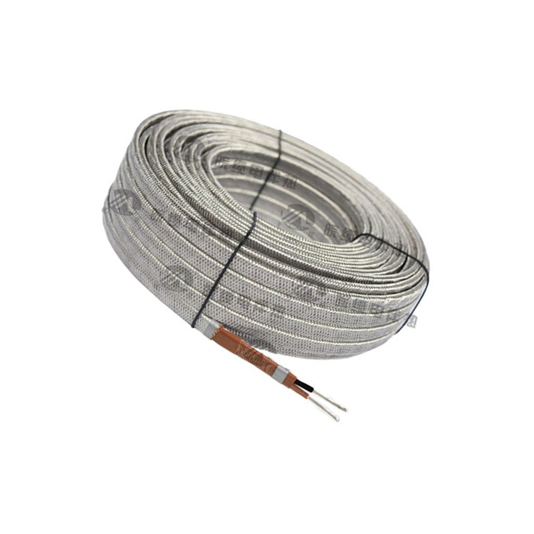
HWL/HGL ParallelConstant Power Electric Heat Tracing TapeAvailable in two types: reinforced and standard. The reinforced type features an additional protective sheath on the outside compared to the standard type.Electric Heating CableThere are three-core electric heat tracing cables, two-core electric heat tracing cables, and the two-core cables are further divided into 380V and 220V versions. The power range is 10W to 60W per meter. The HWL/HGL parallel constant power electric heat tracing cable specifications are the same as the general RDP type, and are superior to the standard RDP type. The HGL constant power parameters are the same as the general RGP type, and also superior to the standard RGP type.
Product Structure
The resistance wire is connected in parallel, and the heating of the pipes is achieved through the heat generated by the resistance wire during operation.
Woven layers available: "Alloy wire" and "Tinned copper wire"; materials vary, prices differ.
Product Applications
The HWL/HGL parallel constant power electric tracing heater is mainly used for pipe systems, storage tanks, valves, and pump bodies in the oil, chemical, power, and metallurgy industries, for heating, frost prevention, or maintaining process temperatures of instrument pipelines. Suitable for tracing insulation of long-distance, large-diameter pipelines. It can be used in ordinary and explosion-proof areas of Class I, II, 2 zones.
Working Principle
Two parallel Ni-Cu braided wires are insulated with a fluorine compound layer, serving as the power bus. Nickel-chromium alloy heating wires are wound around the outer insulation layer, with焊接 performed at fixed intervals to form a continuous shunt resistance. Once the copper power bus is energized, the individual shunt resistances heat up, creating a continuous heated electric tracing system that can be cut to any length.
The power bus consists of two or three parallel insulated copper conductors, which are wrapped with heating wires on the surface of the main insulation layer. These heating wires are connected to the bus at regular intervals (i.e., the length of the heating section), forming a continuous parallel resistance. Once the bus is powered, each parallel resistance heats up, thus creating a continuous heating strip. It can be cut to any length during use, but overlapping use is not allowed. It should be used in conjunction with a temperature control device. As can be seen from the diagram, the parameters of the constant power electric tracing heater are mainly composed of parts such as the bus, insulation layer, inner sheath, heating core, outer sheath, shielding layer, and reinforcing layer.
Product Features
1. No starting current, constant power.
2. Lengthy usage, single direction length up to 300 meters, bidirectional usage up to 600 meters.
3. No degradation; lifespan is approximately 3 years longer under the same conditions.
4. In medium to long pipeline and large tank applications, due to the longer length of this electric tracing heater, the number of circuits is reduced, resulting in a lower overall cost.
5. This electric heat tracing must be used in conjunction with a thermostat or other temperature control device.
6. During installation, this electric heating cable should not be crossed or overlapped, and knotting is strictly prohibited to prevent the resistance wires from being compressed together.
7. This electric heating tape has a minimum recommended length for use, typically not less than 3 meters.
8. Do not mix with steam heating.
High temperature resistance level, capable of withstanding up to 255 degrees Celsius.
Installation Instructions
Design Drawing
A complete set of design drawings should be available prior to construction, including the following information:
Line Number, power supply points are indicated by squares.
Length of electrical tracing required per meter of pipe length (unit: meters) is the winding coefficient.
Heating System Auxiliary Materials List
Design considerations include parameters and specifications of the insulation material used.
(II) Pre-construction Preparation
(A) Pipeline and Tank System
The pipeline and tank system, along with the equipment, have been fully installed.
The rust and corrosion preventive coating has dried completely.
The pipeline and tank system construction specifications are consistent with those shown in the design drawings.
Remove all burrs and sharp edges.
(B) Electric Heating Tapes and Accessories
Is there any damage or breakage on the surface of the electric tracing tape?
The electrical heating tape has good insulation properties (insulation resistance is ≥100MΩ when tested with a 1000VDC megger).
The electric trace heating and all accessory models and design requirements are consistent.
(3) Specific Construction Methods
Single-strand electric heating tape installation method
Secure the electric heat tracing with pressure-sensitive tape, fixing it every approximately 50 cm along the pipeline.
When laying flat, position the electric tracing tape as close as possible to the lower 45-degree side of the pipeline.
预留 100cm long electric heat tracing at the power supply points and end of the line.
Wiring according to the designed twist factor (for integer coefficients, lay flat to minimize junctions).
All heat sinks (such as brackets, valves, flanges, etc.) should be pre-drilled to the required length of electric tracing as per design specifications, wrapped around the heat sink body, and secured. The following points should be noted:
The heat sink should have the required length of electric tracing for the design.
* Constant power electric heating cables must not be overlapped or used in a crisscross manner.
The wrapping method should allow for the easy removal of the heat sink for maintenance or replacement as needed, without damaging the electric tracing or affecting other circuits.
At the locations where two-way or three-way fittings are used, each end of the electric heat tracing should have a reserved length of 100 cm.
Spiral Wound Wire
For a twist factor of 1.5, a 4m pipe requires 6m of electric heat tracing. During installation, first secure the two ends of the 6m electric heat tracing to a 4m section of the pipe. Then, wrap the slack heat tracing around the pipe and secure it in place.
Multiple electric tracing installation method
Design drawings specify a winding factor of (n=1,2…), generally used on large-diameter pipelines, with the following method:
The electric tracing heater is wired from one end of the pipeline to the end, then back to the starting point, the number of turns equals the coefficient. (But note the maximum length used.)
The electric tracing heating is installed by alternating wiring from one end of the pipeline to the end, equal to the coefficient, or by using a winding installation method.
Parts installation
The seals used must be compatible with the electric tracing heating and combined with waterproof sealant.
Power distribution boxes should be as close as possible to the power supply end of the pipeline.
Prepare wire ends according to the accessory installation instructions.
Each line end should leave a small section of electric tracing heat for future maintenance purposes.
Inspection and testing of thermal insulation materials prior to installation:
Inspect the surface of the electric tracing heater for any damage.
Inspect all accessories for complete installation.
* Test each individual circuit end with a megger to ensure good insulation performance.
Record the shake test results on the installation record form.
Insulation installation
Immediately install the insulation layer after the electric tracing heating installation test, and pay attention to the following points:
The materials, thickness, and specifications of the insulation used comply with the requirements of the design drawings.
Insulation materials must be dry during construction.
The insulation should be covered with a waterproof outer shell.
Avoid damaging the electric heating tape during the installation of the insulation layer.
After the thermal insulation is installed, an immediate insulation test should be conducted on the electric heat tracing.
Additional warning labels indicating "Contains Electric Heat Tracing" must be applied on the insulation layer, along with noting the locations of all accessories.
Design Description
Section 1: Design Parameters to Be Determined
1) Maintain temperature for pipeline requirements, Tv (°C), select 10°C.
2) Extremes in low temperatures over the years have been as low as -25℃.
3) Outer Diameter of Pipe (mm):
4) Types and thickness (mm) of insulation material for pipelines; Rock wool δ=50mm
5) Pipeline is outdoors (or indoors)
6) Is the environment explosion-proof: Non-explosion-proof
7) Steam sweeping or heating (or high operating temperature of the medium) available?
II. System Heat Dissipation Calculation:
For example, with DN108 pipeline.
Step 1: Calculate the actual heat dissipation of the pipeline, QT.
QT=1.3×2π×(Tv-Td)/[1/λ•Ln(Do/Di)+2/(Do×α)]
QT - Thermal loss of a pipeline per unit length, W/m
Tv - Maintenance temperature of the pipeline (°C)
Td - Low Environmental Temperature °C
λ - Thermal conductivity of insulation material (W/(m•℃))
Do — Outer Diameter of Insulation Layer (Do = Di + 2δ) mm
Di - Insulation inner diameter mm
δ - Insulation thickness mm
α -- Heat transfer coefficient from the outer surface of the insulating layer to the atmosphere (W/㎡℃) is related to wind speed ω (m/s)
α=1.163(6+3ω1/2) W/( ㎡℃ )
The calculated actual heat dissipation of the DN108 pipe diameter is QT = 50.5 W/m.
Step 2: Electric Trace Heating Wrapping Factor
Select the HBL3-J3-30 electric tracing heater. The heat dissipation of the pipe is 50.5W/m at 10°C. Due to the electric tracing heater being applied to the outer wall of the pipe, the heat transfer efficiency is lower, approximately 70~85%. Considering a safety margin of 20~40% on top of the calculated heat loss for maintaining the temperature, a constant power electric tracing heater with a rated power of 30W/m is selected. Therefore, for every meter of DN108 pipe, 2 meters of HBL3-J3-30 tracing heater are required.
Step 3: Electric Trace Heating Installation Coefficient
1) The required hot line length for the valve is equal to the valve coefficient multiplied by the hot line length required per meter of pipe.
Each flange requires a heat trace length equal to twice the flange diameter multiplied by the number of heat trace units required per meter of pipe.
3) At locations with large quantities of pipe fittings, additional electric tracing should be installed to ensure that these areas do not freeze.
Each electric heating cable accessory should have a reserved extra length of at least 1 meter for wiring and future maintenance.
5) During installation, varying tension in securing the electric heat tracing can result in a certain degree of error in the actual installed quantity of the heat tracing.
In summary of the above five points: The installed quantity of electric tracing heating cables is calculated by multiplying the design quantity by the installation coefficient of 1.20 to 1.50.
Step 4: Electric Heat Trace Cable Quantity Count
Based on the pipeline count, determine the total quantity of electric heating tapes, and compile the total quantity of electric heating tapes for all pipelines.
Step 5: Determine the quantity of electrical distribution circuits and accessories
Based on the drawings, determine the number of circuitry and accessories for the distribution box, and establish the location of the distribution box according to the on-site pipeline layout. The selection of the distribution box must take into account the on-site electrical capacity and the number of electric tracing belts, as well as the maximum usage length of the electric tracing belts. When determining the circuitry, consider not only the on-site layout but also the maximum usage length of the electric tracing belts, as well as the rated current of the power supply junction box and the temperature controller.
Determine the quantity of power junction boxes
The number of power junction boxes is determined by the number of circuits. Generally, the number of power junction boxes (ZDJH) required should match the number of circuits needed for electric tracing design. For instance, if a certain electric tracing project is designed with 40 circuits, then 40 power junction boxes are needed. Considering spares, an additional 10% allowance should be added, meaning a total of 45 power junction boxes are designed.
Determine the number of intermediate junction boxes
The determination of intermediate junction box quantities usually involves assessing site-specific conditions. For instance, the number of pipe tees would determine the quantity of T-type junction boxes (ZJH-3). As for straight-type junction boxes (ZJH-2), they are typically taken as 20% of the power junction box count, with on-site usage being the definitive factor.
On-site temperature controller selection
Field temperature controllers are determined based on the number of loops. Generally, the number of field temperature controllers (BJW51) required should match the number of loops needed for electric tracing design. This also depends on engineering design requirements; some projects require the addition of field temperature controllers, while others may necessitate digital temperature controllers. Therefore, different design plans should be implemented based on the varying customer requirements. For instance, a certain electric tracing project is designed with 40 loops and requires the installation of field temperature controllers (40 units of BJW51 type). Considering backup, an additional 10% allowance should be added, meaning a total of 45 field temperature controllers (BJW51 type) should be designed.
Fixed Pressure Sensitive Tape
The determination of the fixed pressure-sensitive tape (20mm x 20m) usually depends on the diameter and quantity of the engineering pipeline or tank. For instance, if there is a pipeline with DN100 size and a total length of 100 meters, approximately 198 meters of pressure-sensitive tape would be required, calculated as follows: L = d * 3.14 * K1 * K2 * K3 * L1 = 0.1 * 3.14 * 1.5 * 1.4 * 3 * 100 = 198 meters.
diameter: d, safety margin: K1 = 1.5, engineering margin: K2 = 1.2-1.5, K3 ≈ 3 wraps of pressure-sensitive tape around a 1-meter pipe (i.e., securing every 30-50cm), typically 3 or 4, L1 = actual length (height) of the pipe or tank
Aluminum Foil Tape Selection
Aluminum foil tape (50mm x 20m) quantity determination: The quantity of aluminum foil tape is determined based on the length of the electric heating tape. For instance, if a project specifies 1000 meters of electric heating tape, the required length of aluminum foil tape would be L = L1 * K1 = 1000 * 1.3 = 1300 meters. L1 is the quantity of electric heating tape, and K1 is the project coefficient (usually between 1.2 to 1.5).
Determination of the quantity of end connection boxes
The quantity of terminal junction boxes (ZJH) is generally determined based on the number of power junction boxes and tee junction boxes, usually calculated as N = n1 + n2, where n1 is the number of power junction boxes and n2 is the number of tee junction boxes.
Stainless steel belt and clip screws
The determination of the stainless steel belt quantity is primarily based on the number of power junction boxes and temperature controllers. Each power junction box and temperature controller requires two sets of stainless steel belts and fastening screws. The length of each set of stainless steel belts depends on the pipe diameter, for instance, if a power junction box is mounted on a DN100 pipe, the required quantity of stainless steel belts for that junction box would be:
L=d*3.14*k1*2=0.1*3.14*1.5*2=0.942m,
d is the diameter of the pipe, k1 is the safety factor set at 1.5, and 2 represents two sets per power junction box.
Warning Labels and Silicone (or Explosion-Proof Putty)
Warning Labels (110*180) - one per 30 meters of electric heat tracing, one at each end and power junction box. Silicone (TM441) - quantity is 1/3 of the end junction box count. Explosion-proof mortar (1kg/bag) - one kilogram used for every 5 power junction boxes or explosion-proof temperature controllers.