

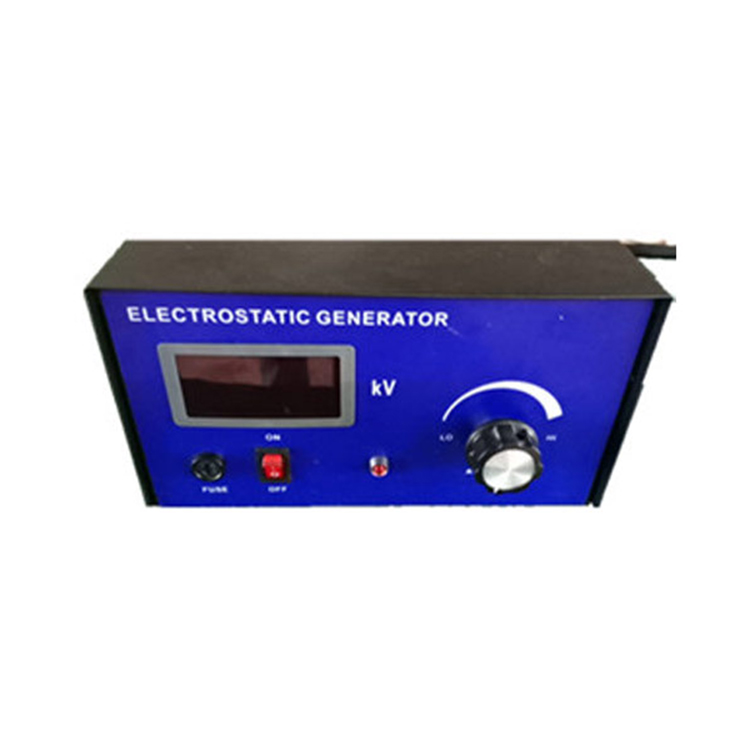
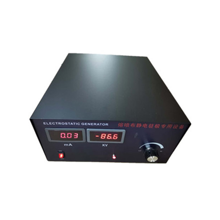

Static Generator
1. Key Points
· The static generator consists of a high-voltage generator and a discharge rod.
· Please read this manual thoroughly before installing and using this product.
Please follow the procedures outlined in this manual to avoid damage, loss, and risk.
2. Safety
Do not use in flammable or explosive environments.
· For safety and proper operation, please ensure the equipment is reliably grounded.
· The high-voltage generator is used to supply high voltage to the discharge rod, which is discharged by its electrodes.
· Do not position the electrode towards the body; do not touch the electrode to avoid electric shock.
3. Usage and Operation
· A high-voltage generator and a discharge rod constitute a static discharge system.
· The high-voltage generator outputs a voltage of 0~30kV.
· High-voltage generators are connected with relays, photoelectric switches, etc., to achieve remote control of high-voltage output.
4. Technical Specifications
Input Voltage: 220VAC 50Hz~60Hz
Output Voltage: 0~30kV
Power Consumption: 40VA
Polarity: Negative (N) / Positive (P)
High-voltage Output Interface: 2 Ports
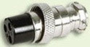
External Control Interface: 3-core aviation plug
5. Installation
5.1. Inspection
Inspect the high-pressure generator for any damage.
Check if all packing accessories are complete.
If you have any questions or doubts, please contact the vendor.
5.2. Grounding
Warning:
Ensure the equipment is properly grounded for safety and normal operation.
5.3. Installation
Warning:
Do not install the high-pressure generator in a damp, dirty, flammable, or explosive environment.
The high-pressure generator must be installed in a location without vibration.
1. The high-voltage generator should be installed in a location convenient for operation and as close as possible to the discharge rod.
2. Secure the high-voltage generator with screws as needed.
Connect the ground wire to the grounding post.
4. Insert the discharge rod plug into the high-voltage generator's output socket and secure it with the included nut.
5. Turn the [ON/OFF] switch to the [OFF] position.
6. Insert the power cord plug into the power socket on the back of the high-voltage generator.
7. Insert the power cord plug into a grounded power outlet.
8. Insert the aviation plug into the aviation socket and secure it with the included nut.
Note:
High-voltage lines must not come into contact with sharp metal parts or bends.
High-voltage lines should be separated from low-voltage lines.
The shorter the high-voltage line, the better.
6. Utilize
6.1 Power On and Power Off
- Power on = [ON/OFF] switch is in the [ON] position.
Power Off = [ON/OFF] switch is in the [OFF] position.

6.2. Initiate and Stop High-Voltage Output
- Activate High-Voltage Output = aviation plug two wires connected.
Stop high-voltage output = aviation plug two wires disconnected.
6.3. Set Output Voltage
Note:
The output voltage of the high-pressure supply unit is designed to meet the requirements, with the principle of not exceeding the necessary level. Excessive voltage can cause sparking and breakdown, affecting normal equipment operation and posing safety hazards.
- The high-voltage supply unit is equipped with a large capacity capacitor. After the high-voltage supply is disconnected, the unit must be powered off for sufficient time or the electrodes must be grounded using a wire to discharge before the discharge needle can be touched during maintenance of the discharge rod.
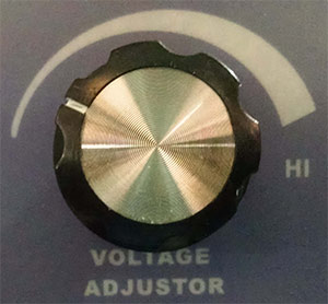
Increase output voltage = Turn the voltage adjustment knob clockwise.
Lower output voltage = Rotate the voltage adjustment knob counterclockwise.
7. External Control
Note:
Through the three-core aviation socket on the back of the high-voltage generator, external control of high-voltage output is achieved by connecting to relays, photoelectric switches, etc.
Pin Function
- Activate high-voltage output = Connect 1, 2 cores.
- Stop high voltage output = Disconnect 1, 2 cores.
Pin Function 1: +12V 2: ON 3: GND
- Activate High Voltage Output = 2, 3 cores connected.
Stop high-voltage output = Disconnect 2, 3 cores.
8. Product Warranty & Service
8.1 Warranty Period
The product warranty is one year from the date of sale. We offer free repairs for quality issues caused by the product's own components, materials, and workmanship within one year.
8.2. Post-warranty service
We are responsible for free repairs on the product after the warranty period expires.
We reserve the right to modify and interpret individual performance parameters and technical improvements of the above products without prior notice.
