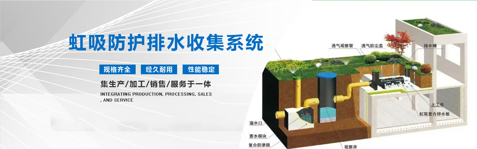


Suction Drainage Collection System Construction Process
1.1 Plotting lines according to construction drawings to determine HXC
1.2 Solder Paste Application: Apply the adhesive evenly along the positioning line.
1.3 Fixed Dedicated Drainage Channels
1.4 Installing Composite Protective Drainage Shaped Sheets
1.5 Geotextile Seam, Glue Sealed
Installed breathable observation tubes and dust covers on June 1st
7.5mm Adhesive Seal Geotextile Cover-Specific Drainage Channels
August 1: Vertical siphon drainage pipe installed alongside the garage.
1.9 Install sedimentation wells, reservoirs, and inspection wells
On 1/10, the rainwater recycling collection system was installed according to the design drawings, connected to the drainage pipe at the outlet of the rainwater sedimentation well, and the overflow pipe was connected to the municipal drainage network.
11/1 Inspection and Acceptance
Dec. 1st, Earthwork Backfill
Construction Methods and Precautions
2.1 Ground-level cleaning: Waterproofing layer passed inspection and maintains a clean, dry surface.
2.2 Based on the design drawings, locate the drain outlets and set up the dedicated drain channels. Then, plan the positioning and mark the lines according to the drawings to determine the placement of the dedicated drain channels.
2.3 According to the marking, lay the adhesive tape (double-sided self-adhesive) over the waterproofing layer. In low temperatures, use a torch or hot air welding gun for thermal melting fixation, and be mindful to protect the underlying waterproofing.
The 2.4 drain channel is securely mounted to the StickyBoss.
2.5 According to the design drawings for the drain outlet position and the setup of the specialized drain channels, lay the composite protective drain sheets in a streamlined manner to meet the overall drainage direction.
2.6 The long and short edges of the composite protective drainage non-standard sheet are firmly bonded with AdhesiveMaster.
2.7 The 2.7mm composite protective drainage geomembrane features a lap width of 100mm, sealed with special adhesive to form an integrated waterproofing protection system. (JGJ 155-2013 Technical Code for Green Roof Engineering, P38 6.5.1.5)
In the case of 2.8 composite protective drainage non-standard sheets encountering a counterbeam, they can be fully covered and sealed. Alternatively, the counterbeam can be leveled, and then the composite protective drainage non-standard sheets can be laid. The upright walls, window wells, and other areas connected to the garage roof deck require an upward treatment of 500mm.
On 2.9, according to the design location on the drawings, installation of breather observation pipes, dust-proof breather caps, etc., with sealed joints using special glue. (Drilling for special drainage channels - installing breather observation pipes - securing with clamp bands - installing dust-proof breather caps)
2.10 Geosynthetic clay-lined geomembrane, covering the dedicated drainage channel.
2.11 After the entire ceiling of the garden shed and other areas are fully laid, according to the design drawings, the outlet locations are determined, siphon drainage pipes are installed to connect to the dedicated drainage channels, and sealed with special adhesive.
2.12 As per the design drawings, install sediment observation wells (detailed deepened drawings).
2.13 As per the design drawings, the installation of water storage module sets and other products is in progress to form the water storage pond of the rainwater collection system (detailed refined drawings). 2.14 Preparations for the installation of the plastic water storage pond.
2.14.1 Excavator digging foundation pit, constructing concrete base (overall responsibility)
2.14.2 Laying Geotextiles and Geomembranes
2.14.3 Special protective measures are taken at the corners of the 2.14.3 plastic water storage modules. The geotextile is sealed using a welding machine for hot melt welding, ensuring that the welding joints are airtight with no leaks. The seams of the geotextile are treated with adhesive sealing.
2.15 Assembly and Installation of the Water Storage Module
2.15.1 The plastic water storage modules were installed according to the design specifications and dimensions, ensuring the stability of the connections. 2.16 Installation of the inspection well
2.16.1 Per design specifications, drill holes on the sealed modules. Install manholes, ensure complete sealing with waterproof glue at the junction of the well wall and the geotextile membrane, prevent any leakage, and properly secure and support the pipeline.
Key Operation Points and Technical Requirements
3.1 Concrete protective layer is not required on the top deck; high molecular protective drainage sheets can serve as a flexible protective layer, providing flexible protection.
3.2 The high polymer protective drainage non-standard sheets are laid uniformly in the same direction as the drainage.
3.3 The high polymer protective drainage sheet uses flat seam bonding, with a bonding width of 120mm. (JGJ 155-2013 Technical Code for Green Roof Engineering, P38 6.5.1.5)
3.4 The flat space formed by the 3.4 high polymer protective drainage non-standard sheet and the plastic siphon drainage channel maintains an overall raised platform for unobstructed drainage.
3.5 High polymer protective drainage non-standard sheets are laid along the edge of the ceiling, with a self-adhesive polyester geotextile filter layer on the roll material. The edges of the polyester geotextile are bonded together, with a bonding width of 150mm. The primary purpose is to prevent mud flow beneath the drainage board, ensuring unobstructed drainage.
On buildings above the roof of the underground parking garage, such as when laying high polymer protective drainage sheets on the side walls of ventilation shafts, the sheets need to be flipped up (150mm). The polyester geotextile should be flipped up and inserted into the gap between the high polymer protective drainage sheets and the wall by 100mm.
The 3.7 garage rooftop edge features rainwater collection wells, which uniformly collect seepage and direct it into plastic collection trays, connecting to the municipal drainage pipes for discharge.
During construction on 3.8, avoid direct driving of construction vehicles over the high molecular protective drainage sheets. Fully loaded labor vehicles should not walk directly on the laid materials. If necessary, use laid boards to form a path to prevent damage to the high molecular protective drainage sheets.
Ensure backfilling is timely on 3.9 to prevent damage to high molecular weight protective drainage sheets and polyester geotextiles by other trades. Construction machinery laying and filling must not come into direct contact with the high molecular weight protective drainage sheets; equipment must be placed only after covering with soil.
