


Rotary Membrane Oxygen Remover Overview and Applications:
With the rapid development of the power industry and the continuous advancement of science and technology, our country's early-operational deaerators, such as spray pad and spray packing types, as well as the rotating film type, have shown their inadequacies more and more, mainly manifested in poor deaeration efficiency, uneven heat exchange, low adaptability, and high steam consumption, unable to adjust with changes in operating conditions and loads. Our company's improved rotating film deaerator is a newly structured deaerator that has been researched and promoted in recent years. Its design primarily changes the original jet type to a rotating jet film type, integrating the rotating film and bubble condensation into one, a novel deaerator. It features high deaeration efficiency, uniform heat exchange, low steam consumption, stable operation, good adaptability, and does not have stringent requirements for water quality and temperature. Moreover, it can operate beyond its capacity.

Operating Principle:
The new type of spinning film improved oxygen removal equipment features heat and mass transfer methods different from existing spray plate, water film, spinning film, and atomization methods. It primarily integrates three heat transfer methods—jet, rotating film, and suspended bubble boiling—into one efficient process. The new spinning jet film tube has a high resolution capability, causing the liquid film to strongly rotate and draw in a large amount of steam along the tube wall, enhancing heat exchange and mass transfer functions. It changes the directional bubble boiling to suspended bubble boiling, raising the entrainment (splashing) point at high steam velocities in each layer while maintaining the gas channel. It condenses the three independent heat and mass transfer devices into one, completing the process within the components of a single unit.
Section 3: Applications and Models of the New Type of Spiral Membrane Oxygen Remover
The MCY-, MCYG- series new type oxygen removal deaerator (hereinafter referred to as the deaerator) uses steam extracted from a steam turbine to heat the boiler feed water to the saturated temperature at the corresponding deaerator working pressure; it removes oxygen and other gases dissolved in the feed water, preventing and reducing corrosion in the boiler pipes, economizers, and other auxiliary equipment.
The model is composed of two parts: the汉语拼音alphabet and the main characteristics of the deaerator (processing capacity T/H).
For example, MCYG-225T/H indicates a high-pressure spinning film deaerator capable of treating water at a rate of 225T/H.
Product Specifications:
New Type Spiral Membrane Oxygen Removal Unit Common Specifications and Models
Model | Deoxygenator Rated OutputT/h | Water Tank Effective Volumem3 | Operating Temperature℃) | Work pressureMpaPressure Rating | Inlet Water Temperature℃) | Design Temperature℃) | Net Weight of Equipmentkg) |
MCY-10 | 10 | 5 | 104 | 0.02 | 20 | 250 | 3680 |
MCY-20 | 20 | 10 | 104 | 0.02 | 20 | 250 | 4570 |
MCY-35 | 35 | 15 | 104 | 0.02 | 20 | 250 | 5616 |
MCY-40 | 40 | 20 | 104 | 0.02 | 20 | 250 | 8320 |
MCY-50 | 50 | 25 | 104 | 0.02 | 20 | 250 | 9556 |
MCY-75 | 75 | 25 | 104 | 0.02 | 20 | 250 | 12200 |
MCY-85 | 85 | 35 | 104 | 0.02 | 20 | 250 | 12200 |
MCY-130 | 130 | 40 | 104 | 0.02 | 20 | 250 | 16250 |
MCY-150 | 150 | 40 | 104 | 0.02 | 20 | 250 | 17800 |
MCY-300 | 300 | 70 | 104 | 0.02 | 20 | 250 | 23885 |
We can custom design any specification of deaerator for the user. Specific dimensions and parameters are detailed in the equipment drawings. | |||||||
New Type Spiral Membrane Oxygen Remover, commonly used high-pressure oxygen remover specifications and models:
Model | Deoxygenator Rated OutputT/h | Water Tank Effective Volumem3 | Operating Temperature℃) | Work pressureMpa(gauge pressure) | Design Temperature℃) | Net Weight of Equipmentkg) |
MCYG-150 | 150 | 40 | 158 | 0.5 | 300 | 19250 |
MCYG-180 | 180 | 50 | 158 | 0.5 | 300 | 21770 |
MCYG-250 | 250 | 70 | 158 | 0.5 | 300 | 26300 |
MCYG-420 | 420 | 120 | 158 | 0.5 | 300 | 42800 |
MCYG-680 | 680 | 180 | 158 | 0.5 | 300 | 62900 |
We can custom design any specification of deaerator for the customer, with specific dimensions and parameters detailed in the equipment drawings. | ||||||
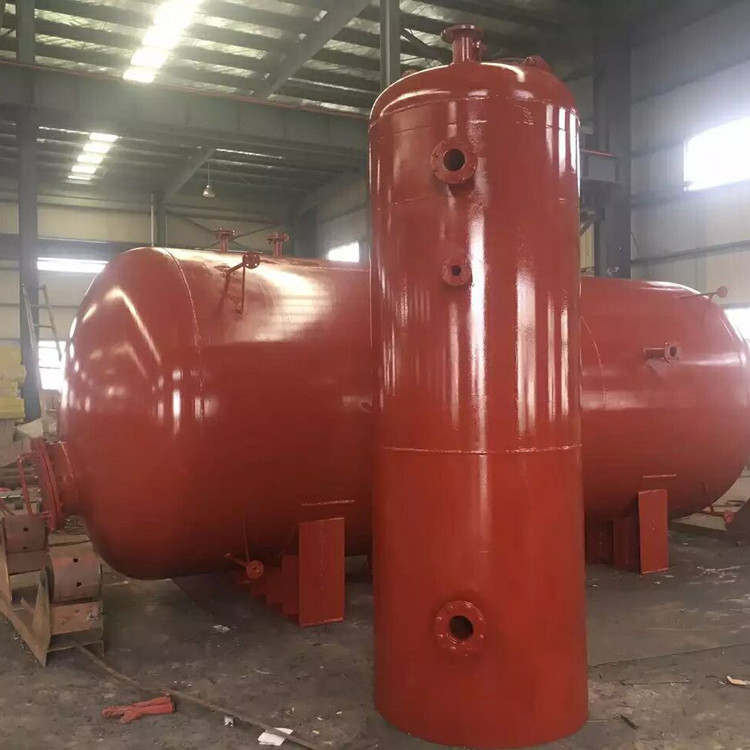
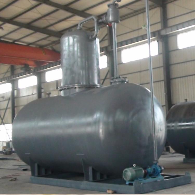
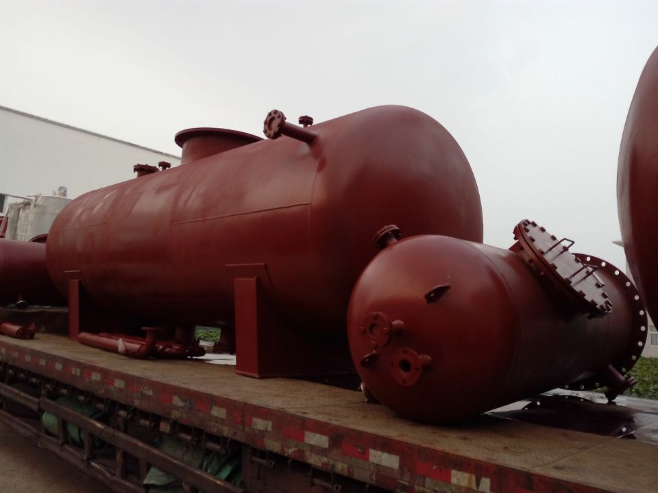
Product Structure:
The structure of the new-type spiral membrane oxygen remover mainly consists of the outer shell, steam-water separator, new-type spiral jet atomizer, sprinkling grate assembly, regular liquid-gas grid, water tank, and other components.
1. New type of spiral membrane oxygen removal reactor shell: It is welded from a cylinder body and a stamped elliptical head.
2. New Type Spiral Membrane Oxygen Remover: This device replaces the original old-style oxygen remover's conical hat structure design, eliminating the issue of steam with water being discharged from the oxygen remover.
3. New Type Spiral Membrane Oxygen Remover: Composed of a water chamber, steam chamber, film-forming tube, condensate receiving pipe, make-up water pipe, drain pipe, and primary steam inlet pipe. New type
The spiral membrane deaerator has added a water film guiding device inside the spiral jet membrane tube, which can maintain strong film reduction even under low-load operation, keeping the spiral jet skirt. Condensate, chemical make-up water, and water emerging from the lifting tube in a spiral shape are sprayed out at a certain angle, forming a water film skirt. This skirt is then heated to near the saturation temperature under the deaerator's operating pressure (i.e., 2-3℃ below the saturation temperature) by contact with heating steam introduced through the primary heating steam inlet and secondary heating steam rising from the water tank via the liquid-vapor grid and water grate assembly. This process performs rough deaeration. Generally, this lifting section can remove most of the oxygen content from the feedwater.
4. New Type Spiral Membrane Oxygen Remover Spray Bar Assembly: Composed of several layers of interlaced angular steel components, the feed water after coarse deoxygenation in the film-forming section and the mixture of high-pressure drain water here are subjected to a second distribution, forming a uniform spray rain-like pattern that falls onto the liquid-gas mesh below.
5. SW-type Packed Bed Oxygen Remover with Novel Spiral Membrane: Composed of many identical units, it forms a cylindrical body with SW-type mesh corrugated packing. This structured packing retains the advantages of both wire mesh corrugated packing and perforated plate corrugated packing, while also offering a larger surface area, lower pressure drop, greater operational flexibility, high separation efficiency, low energy consumption, and will never fall off. Here, feedwater is fully contacted with the secondary steam, heated to saturation temperature, and deeply deoxygenated. The low-pressure atmospheric oxygen remover ≤10PPb, and the high-pressure oxygen remover ≤5PPb.
6. New Type Spiral Membrane Oxygen Remover Water Tank: Deoxygenated water is collected at the bottom of the deoxygenation head and transferred to the water tank. The deoxygenation tank is equipped with a designed powerful heat exchange and re-boiling unit, which boasts strong heat exchange, rapid water temperature increase, deeper deoxygenation, reduced tank vibration, lower noise, and extended equipment lifespan.
Technical Retrofit - Installation, Operation, and Maintenance of Spiral Membrane Oxygen Remover
1. Installation of deaerators, water tanks, and accessories should be conducted according to the MCY-MCYG deaerator system diagram and this manual.
2. After the deaerator and water tank are welded, a hydrostatic test should be conducted, with the test pressure in accordance with relevant regulations.
3. Prior to the official operation of the new type of spiral membrane oxygen removal unit, the valve should be adjusted so that it automatically opens when the pressure inside the equipment reaches the specified value.
4. Adjust the automatic pressure regulator, maintaining the deaerator pressure within the specified range and the water tank outlet temperature within the designated temperature range. If the deaerator pressure exceeds the above range during operation, check for any faults in the pressure regulator. The butterfly valve's normal water level is ±200mm, which is the extreme water level. Open the high-level drain valve (electromagnetic gate valve) to drain when the water level is high, and it should automatically close when the water level decreases. During operation, frequently check the responsiveness of the electric water level control system and the suppleness of the make-up water regulating valve.
5. During the operation of the new-type spiral membrane deaerator, the feed water should be heated in the film-forming section to a temperature close to the saturation temperature under the deaerator's operating pressure (i.e., 2-3℃ below the saturation temperature).
6. Adjust the exhaust valve opening to achieve an exhaust gas volume of approximately 2-3kg per ton of deoxygenated water.
7. The water tank level gauge should be flushed regularly to prevent contamination.
8. When the deaerator is operating, the inlet valve should be opened first, followed by the heating steam valve. When stopping, do the opposite: close the steam inlet valve first, then the water inlet valve.
9. When inspecting the deaerator, the water in the tank should be drained and cleaned.
10. When the deaerator is to be shut down for an extended period, appropriate anti-corrosion measures should be taken.
Application Scope:
Our company supplies complete sets of new-type spiral membrane deaerators and also undertakes technical renovation projects for the deaerators of the power plants, including spray tray, spray packing, spiral membrane, and water film deaerators.
Based on our company's past experience with technical upgrades to deaerators in power plants, thermal power plants, and self-provided power plants across various regions, converting spray tray, spray packing, water film, and rotating film deaerators into the new rotating jet film deaerator has been successful and yielded significant results.
Modifying the existing deaerator is quite convenient. Simply utilize the shell and end cap of the original deaerator head, remove all internal components such as the spray tray or spray packing, as well as the rotating film and water film parts. Retain the lower steam inlet dish, and then add a regular liquid-gas mesh and a water grate assembly above it at a certain position. Seal and secure it with a circular pressure plate to prevent water-gas short-circuiting during future operation. Next, detach and weld the end cap to the cylinder body, install the centrifugal atomizing film former, and connect the remaining components according to the provided modification scheme. The job is then complete, and after passing inspection, it can be put into operation.
During the renovation process, the diameter of the deoxygenation head is generally not increased; its height can be appropriately adjusted based on the specific circumstances, usually only raised or welded at the original height.
