


Product Application
A desuperheater is designed to expand and reduce the pressure of the condensate line, separating steam and condensate. The steam is then introduced into a heat exchanger or deaerator to maximize its thermal energy, while the condensate is directed to a condensate tank for regular addition to the feedwater system. Its primary function is to lower pressure; if high-pressure steam is directly fed into a condenser, it can cause overpressure. This device can reduce pressure, prevent overpressure, and also includes a temperature-reducing device to lower temperatures.
Mechanical drain valves, such as free floating ball, lever floating ball, and inverted bucket types, utilize the principle of buoyancy for operation. They can automatically differentiate between steam and water and are commonly used in scenarios requiring continuous drainage with high flow rates, where drained water is collected and reused. The lever floating ball and inverted bucket drain valves have complex structures, while the free floating ball drain valves have a simple design and are leak-proof, typically used for pipeline drainage or equipment drainage.
Thermodynamic (disc type, pulse type) trap valves utilize aerodynamic principles to open and close the valves by the pressure drop generated from the redirection of vapor flow. They are suitable for applications with low flow rates, high differential pressure, and less stringent requirements for continuity. These valves have a simple structure, exhibit pulsating leakage, and are generally used for pipeline drainage.
Model Representation Method:
S K (Hydrophobic Expander)
XX (Geometric Volume m³) - XX (Number of Modifications)
Product Structure:
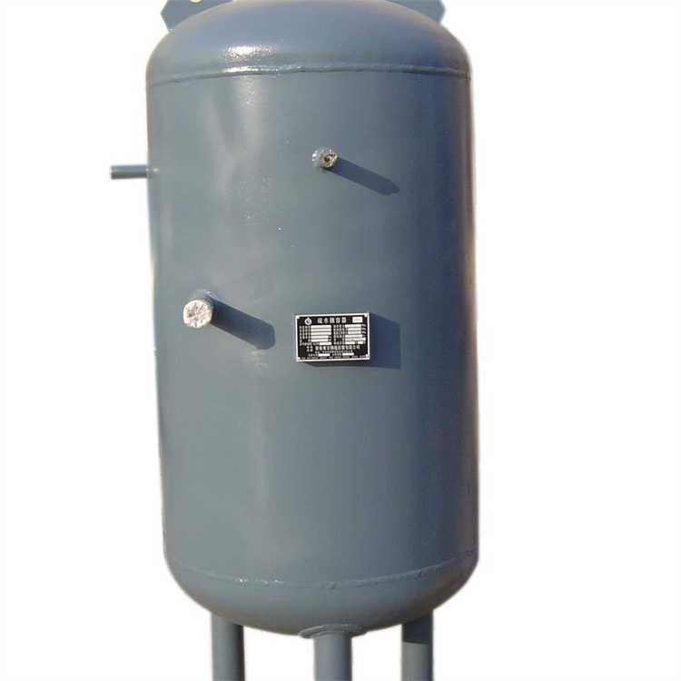
The water-repellent expansion vessel consists of an outer shell, multiple inlet pipes, and a water-vapor separator. Optional accessories such as manholes, handholes, and cooling water pipes can be added as needed for easy maintenance and safe operation of the equipment.
Order Instructions:
Expansion tanks are available in continuous discharge, scheduled discharge, and condensate drainage types.
Expansion tanks are categorized by structure into vertical and horizontal types, and are generally sized by volume.
Rowed usage:
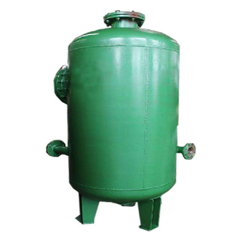
The continuous effluent expander is designed to expand and reduce the pressure of continuous boiler effluent, separating it to produce steam for utilization, thereby enhancing the thermal economy of the power plant.
Composition Structure:
1. Housing 2. Water Inlet Distributor 3. Steam and Foam Removal Device 4. Safety Relief Device 5. Liquid Level Indicator 6. Liquid Level Control Assembly. (Note: The Safety Relief Device and Liquid Level Control Assembly are not included in the supply scope. If a matching set is required, it must be specified in the contract.)
Main technical specifications:
Specification Model | Geometric Volume m3 | Design Pressure MPa | Design Temperature: °C |
LP-0.7 | 0.7 | 0.5 | 270 |
LP-1.5 | 1.5 | ||
LP-3.5 | 3.5 | ||
LP-4 | 4 | ||
LP-5.5 | 5.5 |
Note: Various specifications of continuous rows can be designed upon customer requirements; simply provide the technical parameters.
Dedicated Rack Purpose
Expand and reduce the pressure of the regular boiler drainage; separate and utilize the steam to improve thermal economy.
Composition Structure: 1. Shell 2. Inlet Water Distributor 3. Steam and Foam Separator 4. Access Hole
Main specifications and technical parameters:
Specification Model | Geometric Volume m3 | Design Pressure MPa | Design Temperature: °C |
DP-0.8 | 0.8 | 0.2 | 250 |
DP-1.5 | 1.5 | ||
DP-3.5 | 3.5 | ||
DP-7.5 | 7.5 | ||
DP-15 | 15 |
Note: Various specifications can be designed according to customer requirements, provided technical parameters are provided.
Hydrophobic Expansion Vessel
Application: It expands and reduces the pressure of condensate in the drainage pipeline, separates steam and condensate, introduces steam into a heat exchanger or deaerator to fully utilize thermal energy, while the condensate is directed to a condensate tank for regular addition to the feedwater system.
Structure Composition: 1. Housing 2. Inlet Pipe 3. Water-Air Separator, etc.
Specification and Model, Technical Parameters
Specification Model | Geometric Volume M3 | Design Pressure MPa | Design Temperature: °C |
SK-0.5 | 0.5 | 0.3 | 300 |
SK-0.75 | 0.75 | ||
DP-1.0 | 1.0 | ||
SK-1.5 | 1.5 | ||
SK-2.0 | 2.0 |