
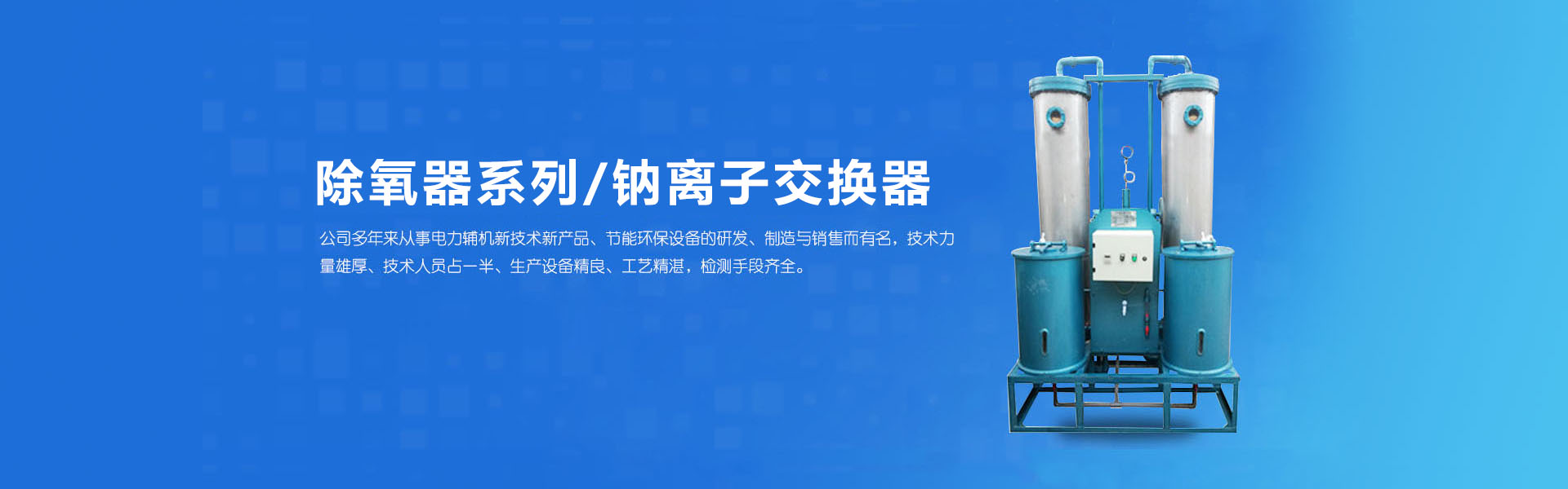


Our company's new-type spiral-membrane improved deaerator is a newly structured deaerator that has been researched and promoted in recent years. The design primarily converts the original jet-type to a spiral-jet membrane type, integrating spiral membrane and bubble collapse into a novel water film deaerator. It boasts high deaeration efficiency, uniform heat exchange, low steam consumption, stable operation, good adaptability, and is not strict in water quality and temperature requirements. Additionally, it can operate beyond its capacity.
Introduction
With the rapid development of the power industry and the continuous advancement of science and technology, the oxygen-removing equipment, such as the early-installed spray fillers with spray plate and rotating film type in our country, has increasingly shown its inadequacies. These are mainly manifested as poor oxygen-removal efficiency, uneven heat exchange, low adaptability, high steam consumption, and inability to adjust with changes in working conditions and load.
Our company's new type of spiral-jet membrane oxygen remover is a newly structured oxygen remover that has been researched and promoted in recent years. Its design primarily transforms the original jet flow into a spiral-jet membrane style, integrating spiral membrane and bubble coalescence into a novel water film oxygen remover. It boasts high oxygen removal efficiency, uniform heat exchange, low steam consumption, stable operation, good adaptability, and is not stringent in water quality and temperature requirements. Moreover, it can operate at about 50% overcapacity.
(II) Working Principle
The new jet-membrane oxygen removal unit features a heat transfer and mass transfer method different from existing spray plate, rotating film, and atomization types. It primarily integrates three heat transfer methods: jet flow, rotating film, and suspended bubble flow, achieving high efficiency. The new jet-membrane tube has great analytical capability and causes the liquid film to strongly rotate and draw in a large amount of steam against the tube wall, enhancing heat exchange and mass transfer functions. It changes the opposite-side bubble flow to suspended bubble flow, increases the steam flow rate and boiling point (splashing) in each layer, and maintains the gas channel. By condensing the three independent heat transfer and mass transfer devices into one, all are completed within a single unit component. Due to its high efficiency and certain special functions, it breaks through the technical performance of existing oxygen removal units. This oxygen removal unit is an improved type of rotating film oxygen removal.
(3) Applications and Models
The MCY- and MCYG-series new type oxygen-removing membranes are heated to the saturation temperature at the corresponding working pressure of the oxygen-removing unit by extracting steam from a steam turbine to heat the boiler feed water; they remove oxygen and other gases dissolved in the feed water, preventing and reducing corrosion in the boiler pipes, economizers, and other auxiliary equipment.
The model is composed of two parts: the Chinese Pinyin letters and the main characteristics of the deaerator (processing capacity in T/H).
For example, MCYG-225T/H denotes a high-pressure jet membrane deaerator capable of treating 225T/H of water.
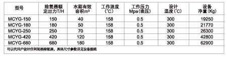
Section 4: Technical Specifications and Matching Parameters
Standard Low-Pressure Deoxygenator Specifications and Models
Standard High-Pressure Deoxygenator Specifications and Models
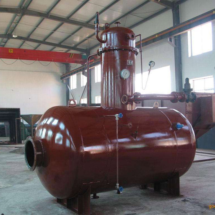
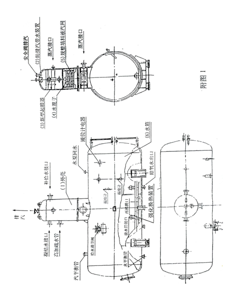
(Five) Structure (Chart 1)
The oxygen separator's structural type is shown in Figure 1. It consists of: (1) Outer Shell, (2) Steam-Liquid Separator, (3) New Type Spiral Jet Atomizer, (4) Shower Grating, (5) Regular Liquid-Vapor Grid, (6) Water Tank.
1. Shell: Welded from the cylinder body and stamped elliptical end caps.
2. Air Separator: This device replaces the original old-style deaerator with a grass hat cone structure design, eliminating the phenomenon of steam discharge with water in the deaerator, reducing the heat loss of the steam discharge to below 1‰.
3. New Type Spiral Atomizer Membrane Evaporator: Composed of water chamber, steam chamber, membrane tube, condensate water outlet, make-up water pipe, drain valve outlet, and primary steam inlet. The new type spiral atomizer membrane evaporator features an increased water film guiding device in its spiral membrane tube, enabling strong film reduction even under low load operation, maintaining the spiral membrane skirt.
Condensate, chemical make-up water, spiral out at a certain angle through demister tubes, forming a water film skirt. It then comes into contact with heated steam introduced from the primary heating steam header and secondary heating steam rising through the liquid-gas network and over the water grate from the reservoir, being heated to nearly the saturated temperature under the deaerator working pressure (i.e., 2-3℃ below the saturated temperature) and undergoing rough deaeration. Generally, this demisting section can remove about 90-95% of the oxygen content in the feed water.
4. Drip Grating: Composed of multiple layers of angular steel pieces arranged in an interlaced manner, the water supplied after the rough deoxygenation in the film-forming section and the high-pressure condensate mixed here are distributed a second time, forming a uniform rain-like pattern that falls onto the liquid-vapor net placed underneath.
5. SW-type mesh corrugated packing: Composed of many identical units, it forms a cylindrical body with a regular mesh structure. This packing retains the advantages of both wire mesh and perforated plate corrugated packing, while also featuring a larger surface area, lower pressure drop, high operational flexibility, high separation efficiency, low energy consumption, and never shedding. Here, the feedwater is fully contacted with the secondary steam, heated to saturation temperature, and undergoes deep deoxygenation. The low-pressure atmospheric deoxygenator has a level of ≤10PPb, while the high-pressure deoxygenator has a level of <5PPb.
6. Water Tank: Deaerated water is collected into the feed water tank located below the deaerator head. The deaeration tank is equipped with a newly scientifically designed powerful heat exchange and reboiling unit, which boasts strong heat exchange, rapid water temperature increase, deeper deaeration, reduced tank vibration, and lower noise, among other advantages. These features enhance the lifespan of the equipment and ensure its safe and reliable operation.
(Six) Connecting Systems and Accessories
Deaerator is welded to the interface ring of the water tank at the installation site, forming a deaeration equipment. The accessories of the deaerator equipment include:
1. Safety valve: Installed on the water tank, this valve automatically opens to relieve pressure when the internal pressure of the equipment exceeds the allowable limit, serving as a safety protection.
2. Pressure Gauge: Installed at the top of the deaerator, monitoring the pressure inside the equipment.
3. Thermometer: Installed at the bottom of the water tank, monitoring the water temperature inside.
4. Butterfly Valve: Installed on the heating steam pipeline, it adjusts the flow of heating steam with the help of an electric regulator to maintain the pressure inside the deaerator within the rated range.
5. Shut-off valve: Installed on the secondary heating steam pipeline; adjusts the flow of secondary heating steam.
6. Regulating Valve: Installed on the chemical make-up water pipe; adjusts the flow of make-up water with the help of an electric water temperature control system; to maintain the normal water level in the tank.
7. Water Level Gauge: Installed on the water tank to monitor the water level inside.
8. Electric globe valve: Installed on the water drain pipe of the water tank, when the water level in the tank exceeds a certain limit, the electric globe valve automatically opens with the help of an electric water level regulating system, diverting the excess water beyond the limit to the overflow tank.
9. Pressure Automatic Regulator: Automatically adjusts the opening of the heating steam inlet flange. It regulates steam flow while maintaining stable pressure within the deaerator.
10. Electric Water Level Regulation System: Automatically adjusts the water supply flow and controls the limit water level release valve (electric gate valve).
11. Monitor the main condensate inside the deaerator: thermometer for chemical makeup water, drain, heating steam inlet, and feedwater, as well as the exhaust gas outlet temperature.
12. Monitor heating steam: pressure gauges for main condensate, chemical make-up water, and drain steam inlet pressure.
The above accessories and parts can be purchased on behalf of our factory, but are not within the scope of supply.
Installation, Operation, and Maintenance
1. Installation of deaerators, water tanks, and accessories should be carried out according to the MCY-MCYG model deaerator system diagram and this manual.
2. After the oxygen separator and water tank are welded, a hydrostatic test should be conducted, with the pressure parameters in accordance with the relevant regulations.
3. Prior to the formal operation, the safety valve should be adjusted to automatically open when the pressure inside the equipment reaches the specified level.
4. Adjust the automatic pressure regulator, maintain the deaerator pressure within the specified range, and keep the water tank outlet temperature within the specified temperature range. During operation, if the deaerator pressure exceeds the aforementioned range, check if the pressure automatic regulator is malfunctioning. Ensure the butterfly valve operates smoothly.
5. Adjust the electronic water level control system to maintain the water level in the tank within ±100mm of the normal level. When the water level reaches ±200mm of the normal level, which is the limit level, open the high-level drain valve (electromagnetic gate valve) to drain water. The valve should automatically close when the water level decreases. During operation, regularly check the responsiveness of the electric water level control system and the drain valve.
6. During operation, the feed water should be heated in the demisting section to nearly the saturation temperature under the deaerator operating pressure (i.e., 2~3℃ below the saturation temperature).
7. Adjust the exhaust valve opening to achieve an exhaust gas flow of approximately 2-3kg per ton of deaerated water.
8. The water tank level gauge should be regularly flushed to prevent contamination.
9. When the deaerator is operating, the inlet valve should be opened first, followed by the steam valve when heating. When stopping, do the opposite: close the steam valve first, then the inlet valve.
10. When inspecting the deaerator, the water in the tank should be drained and the tank should be cleaned.
11. When the deaerator is to be shut down for an extended period, appropriate anti-corrosion measures should be taken.
Section 8: Transform oxygen-removing equipment such as spray fillers, spray disk fillers, and spinning film fillers into new spinning jet film oxygen-removers.
Introduction
Our factory supplies complete sets of new type spin-dry oxygen removal membranes while also undertaking technical renovation projects for power plants related to spray plate, spray packing, and spin film oxygen removal systems.
Based on our factory's past technical upgrades to deaerators in power plants, thermal power plants, and self-provided power plants across the country, transforming spray plate and spray packing water film deaerators into the new swirl film deaerators has been successful and yielded significant results.
(2) Brief Description of the Modified Structure (see Appendix Figure 4)
It can be seen from the image that modifying the existing deaerator is quite convenient.
Utilize the original deoxygenator head's shell and dome section to remove all components, including the spray disk or spray packing, and water film from inside the head, preserving the lower section for the steam tray. Then, add a uniform liquid-gas mesh and grate at a certain position below the steam tray, and seal and secure it with a circular pressure plate to prevent water-vapor short circuits during future operation.
Remove and weld the junction of the head and cylinder into the spin film coater, connect the remaining pipeline components according to the provided modification scheme diagram, and the job is complete. After passing the inspection, the equipment can be put into operation.
During the改造 process, the diameter of the deaerator head is typically not increased; instead, its height is appropriately adjusted according to specific conditions, usually only elevated or welded back to the original height.

(3) Structure:
The oxygen scavenger is primarily composed of the outer shell, steam-water separator, new swirl atomizer, sprinkling grating, ordered liquid-gas grid, and water tank.
1) Shell: Welded from the筒body and stamped elliptical end caps.
2) Air Separator: This device replaces the original old-style deaerator's conical grass hat structure, eliminating the phenomenon of steam discharge carrying water in the deaerator.
3) New Type of Rotating Film Evaporator: Composed of a water chamber, steam chamber, film tube, condensate connection, make-up water pipe, drain connection, and primary steam inlet connection. The new type rotating film evaporator features an enhanced film tube with a water film guidance device, which ensures strong film reduction even under low load operation, maintaining the rotating film skirt.
Condensate, chemically replenished, is sprayed out in a spiral pattern at a certain angle through demisting tubes, forming a water film skirt. It then contacts the heated steam introduced from the primary heating steam header and the secondary heating steam rising through the water-aerated grid and over the water grate from the tank. This mixture is heated to a saturation temperature close to the oxygen-remover's operating pressure (i.e., 2-3℃ below saturation temperature) and undergoes rough deaeration. Generally, this demisting section can remove about 90-95% of the oxygen content in the feedwater.
4) Sprinkler Grating: Composed of multiple layers of intersecting angular steel pieces, it undergoes secondary distribution as the water from the rough deoxygenation section and the water from the high-pressure condensate mixture here, which falls evenly in a sprinkling rain pattern onto the liquid-vapor mesh below.
5) Regulated Packed Bed: Consists of a SW-type mesh with wave-shaped elements of identical open sizes, forming a cylindrical structure. This regulated packed bed retains the advantages of both wire mesh and perforated plate wave-shaped packings, and features a larger surface area, lower pressure drop, greater operational flexibility, high separation efficiency, low energy consumption, and never shedding. Water here comes into full contact with the secondary steam, is heated to saturation temperature, and undergoes deep deoxygenation. The low-pressure atmospheric deoxygenator ≤10PPb, and the high-pressure deoxygenator ≤5PPb.
6) Feedwater Storage Tank: Deaerated feedwater is collected in the feedwater storage tank located below the deaerator head. The deaeration tank is equipped with a powerful heat exchange and reboiling unit, which features strong heat exchange, rapid water temperature increase, deeper deaeration, reduced tank vibration, and lower noise. These advantages enhance the equipment's lifespan and ensure the safety and reliability of its operation.