
 通过中商114认证

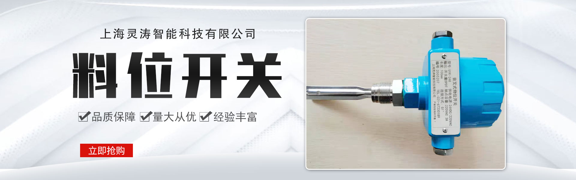
Level SwitchComposed of a reed switch and a float ball with magnetic material inside, one or more reed switches are set within a sealed, non-magnetic metal or plastic tube. The tube is then passed through one or more float balls containing magnetic material, and the float ball's position relative to the reed switch is controlled using fixed double rings.
The float rises or falls with the liquid, using the magnet inside the ball to attract the contact point of the magnetic reed switch, thereby producing an on/off action for level control or indication (the switch is closed when the float is near the magnetic reed switch; it opens when the float moves away). The normally open and normally closed states refer to the condition without liquid. The control circuit is completely isolated from the medium being measured, allowing for level control under high temperature and high pressure conditions. It can be configured for multi-point and remote control as needed, with various connection methods such as flanges and threads, to meet the requirements of different environments. Its wide application range includes industries such as water treatment, chemicals, food, packaging, electronics, ships, textiles, and hydraulics.
A switch is a simple structure and convenient to use.、A reliable level controller, it is smaller, faster, and has a longer working life than typical mechanical switches. Compared to electronic switches, it boasts strong resistance to load surges. It has been widely applied in shipbuilding, papermaking, printing, generator equipment, petrochemicals, food industry, water treatment, electrical engineering, dye industry, and hydraulic machinery.
Level Switch Calibration
(1) The relay operates as follows when the float ball rises and falls through the set upper and lower liquid levels: The relay does not activate when the float ball rises past the lower liquid level, until it rises to the upper liquid level, at which point the relay disengages. Similarly, the relay does not activate when the float ball falls past the upper liquid level, until it falls to the lower liquid level, at which point the relay closes.
(2) The upper liquid level signal is emitted when the float is approximately 1 cm from the bottom; the same signal is triggered when the float is around 1 cm from the top.
(3) Inside the control panel's electrical box, the knob with markings 1-6 is the height adjustment knob, used to adjust the relative height between the upper and lower liquid levels. The small knob with a locking nut in the upper left corner is the zero adjustment knob, used to set the initial lower liquid level at low temperatures.
(4) The principle for determining the adjustable liquid level range is: based on the infrequent operation of the supply solenoid valve during normal operation.
(5) In the refrigeration process, it is only required that the lower liquid level signal be emitted at approximately one-third of the vertical height within the barrel, which allows the main valve to supply the liquid.
(6) When the wire bundle is below -30°C in low-temperature conditions, due to a significant change in resistance, it may not send out signals. In this case, turn the zero-adjustment knob to bring out the lower level signal. After adjusting, tighten the locknut securely.
