


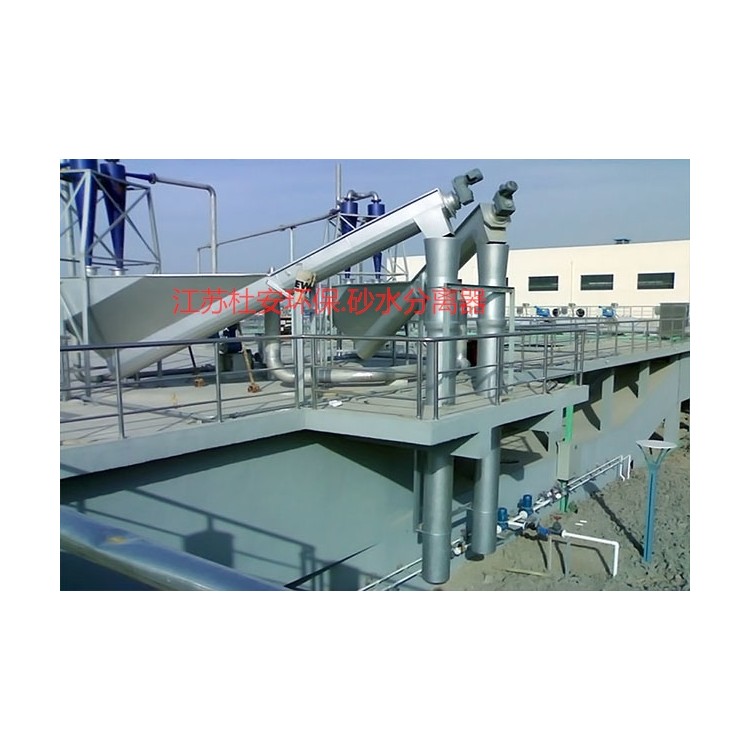
LSSF-260 Sand and Water Separator Price
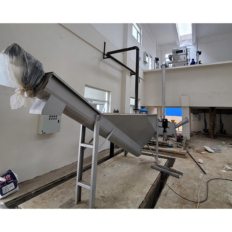
Spiral Sand Water Separator Installation Diagram
Sedimentation Tank Sand-Water Separator Quotation
Duwan Environmental ProtectionLSSF-320Sand and water separator installation and debugging instructions:
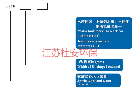
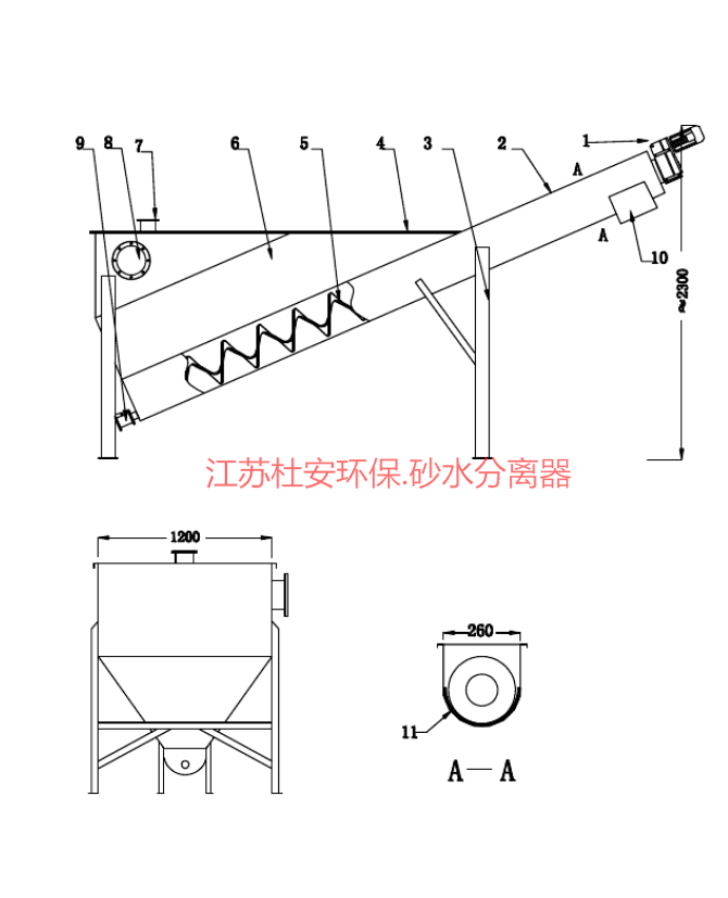
Sand and water separator mainly consists of shaftless spiral, strips.UComprised of moldings, water tanks, flow guides, discharge weir drives, etc.
Installation and Commissioning:
1.If not specified in the order contract, the machine is shipped with a floor stand pre-installed according to the user's installation angle or discharge height, secured with expansion bolts during installation.
2The installation angle error of the equipment is ±1Degree.
3The equipment must not collide or slip during hoisting and effective measures must be taken to protect the stainless steel surface from scratches, wear, and dents.
4Check the reducer oil level before starting up.*First-time use300Change lubricant every hour, continuous operation exceeding16Hourly equipment, thereafter2500Change every hour, operate daily8Equipment hours can be extended to4000Hour(s).
5When power-on testing, it should be started first to confirm no parts are rubbing before entering normal operation.
Sand and water separator usage, maintenance, and care:
1Operators must be trained and qualified before they can operate on the job.
2Equipment is operated in accordance with normal patrol, maintenance, repair, and lubrication management procedures.
3Daily inspections of machine operation are conducted, ensuring no abnormal noises, checking for leaks in the seals, and adding the appropriate amount of bearing grease. Monthly, the oil level in the drive unit gear box is checked and topped up to the required level.
4Every two years: dismantle and overhaul the equipment, disassemble and clean the reducer, replace worn parts, replace seals and worn bushes, inspect and correct the helix, etc.
5.Downtime due to malfunctions should have the cause identified, and the fault resolved before restarting the machine.
6When the machine is idle for three days or more, flush or remove the internal materials to prevent them from drying and caking.
7During winter when temperatures are low, frost prevention is necessary. Blockages and ice should be cleared before operation. If supplied as a set with other equipment, the control buttons are centralized in one control box.

Duwan Environmental LSSF-260 Sand and Water Separator Basic Control Box Requirements
A.2.1 On-siteThe electrical components in the control box must meet the rated interrupting capacity requirement of ≥50kA. All electrical control systems within the box should operate safely, be reliable in action, and switches, buttons, indicator meters should comply with remote/local control requirements.
A.2.2 Component Requirements:
Molded Case Circuit Breaker: Made in China, 50kA breaking capacity.
Miniature circuit breakers: Made in China
Contactor: Made in China
Thermal Relay:
Start/Stop Button and Indicator Light: Domestic.
Terminal blocks: Made in China.
All electrical components must be installed, debugged, and accepted in compliance with the requirements.
All就地control boxes/cabinets are made of 304 stainless steel, with a thickness of not less than 2mm, and equipped with stainless steel door handles on the box/cabinet doors.
2.4 The door locks should be uniformly selected as corrosion-resistant and sturdy alloy locks, with the outer lock being a keyed lock and the inner lock a convenient lock, ensuring that the keys for the same type of lock are identical. The control box panel must also be equipped with a sealed cover with an observation hole covering the indicator lights and buttons, etc., which can be locked to prevent moisture from rain from affecting the components, using silicone rubber seals.
A. 2.5 Enclosure Protection Class: Indoor not less than IP54, outdoor not less than IP56.
A.2.6 Color Identification for Electrical Equipment
Electrical equipment housing color standard is silver. Material is powder coating or 304 stainless steel.
Amongst themThe use of buttons and indicator lights should comply with the relevant regulations in IEC 60073.
LED Indicator
Each circuit breaker panel should be equipped with a red light and a green light to indicate the closed and open states of the circuit breaker, respectively, with a yellow light indicating "auto-trip." A three-color light can be used when indicating for simulated lines.
When using a lighted button for control, the button should be engraved with clear instructions such as "push to open" or "push to close." After the command is executed and the device moves, the light should emit the following colors.
All light colors must conform to the following conventions unless otherwise approved.
Red: Live and actuated positions
Green: No-Pressure or No-Action Position
Yellow: Fault or Abnormal Condition
White: Normal or Standard Condition
Blue: For Other Uses, Label When in Use
Breaker panels and control panels should have a test function for the lights, allowing all lights to be tested while the equipment is in operation. The test operation of the lights will not cause any other equipment to activate.


