

I. Product Introduction
Walk-behind sludge pump, used in wastewater treatment and waterworks for scraping settled sludge from the bottom of the pond into the pump suction port, while walking and suctioning the sludge. Then, the sludge is discharged outside the pond, alleviating the hassle of cleaning the pond bottom. The sludge suction method is customizable to one of three options: siphon, pump suction, or pump-siphon combination. The siphon method uses a submersible pump with a water jet or a vacuum pump to create a vacuum, utilizing the liquid level difference between the sedimentation pond and the sludge discharge channel to pump out the sludge. The pump suction method directly uses a submersible pump to extract settled sludge.
Gearbox: Guomao
Speed Reducing Mechanism: Gearbox
Material: Submerged 304 Stainless Steel, Above Water Carbon Steel
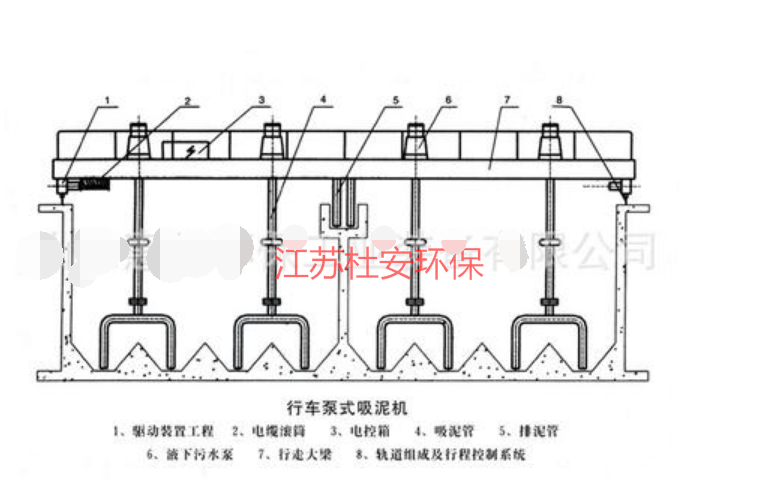
Track-type mobile crane
II. Key Features
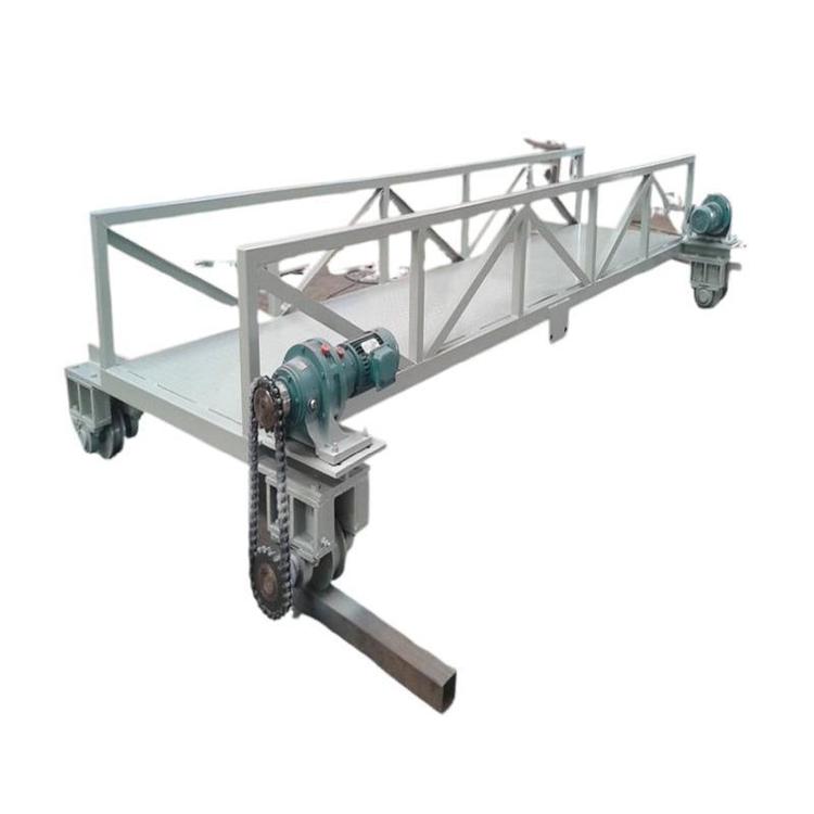
1. The transmission unit is equipped with an shaft-mounted reducer or a flange-direct coupled reducer, featuring a compact design and easy assembly and disassembly.
2. The drive wheel powers the surrounding functions, ensuring the mud cleaner operates over long distances without track biting or climbing.
3. The mud system can be equipped with a backflush device to exclude unexpected issues such as pipeline blockages.
4. Features a non-clogging submersible pump for pump suction or pump siphon two-suction options, with rapid start-up, no need for priming equipment, and simple operation and maintenance. The submersible pump is uniquely connected to the sludge suction system, allowing for maintenance or replacement without stopping the water discharge.
5. Low maintenance volume, small power consumption, and low operating costs; pump selection is reasonable, with stable and reliable operation.
6. Wheel options include rubber, nylon, and steel. Custom sizes available upon request.
Section 3: Working Principle
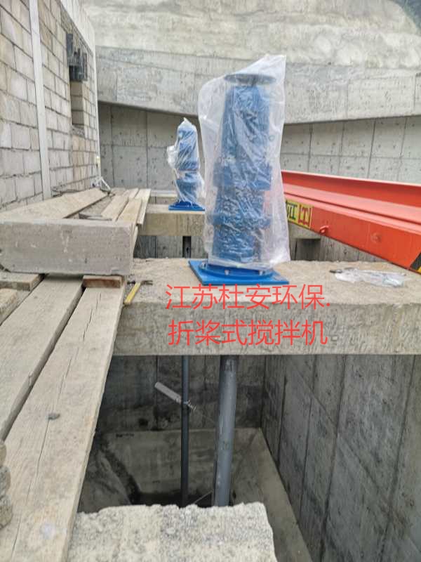
a) Drive System: The sludge pump features a two-stage cycloidal pinion reducer for its drive mechanism, which is directly connected to the wheel shaft via a cross slide coupling, propelling the steel wheels to roll along the poolside track. The stroke switch controls the pump's travel, ensuring continuous back-and-forth movement for sludge suction.
b) Sludge Extraction: The siphon sludge extractor operates using the siphon principle. Before the machine starts, the vacuum pump or water jet is activated to remove air from the sludge pipe, then the pump is turned off. The sludge pipe is opened, and by utilizing the water level difference between the sedimentation tank's inside and outside, the active sludge scraped from the bottom刮板 to the mouth of the sludge extractor is continuously pumped out of the tank. The pump-jet sludge extractor directly discharges sludge using a sludge pump. During operation, the submersible pump is simultaneously started to pump the sludge out of the tank.
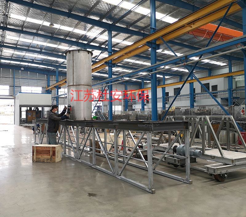
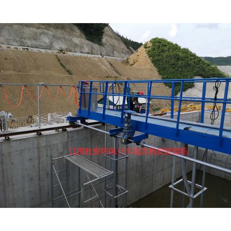
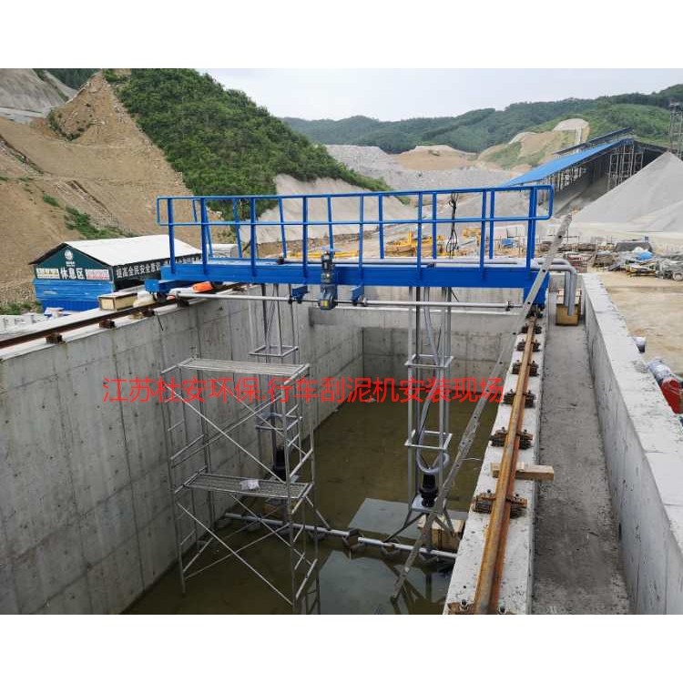
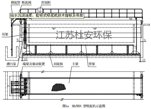
IV. Structural Composition
The mobile sludge pump consists of a working bridge, sludge intake pipe, sludge discharge pipe, submerged sludge pump, driving mechanism, electric control box, upper sliding or slider-type cable line, etc.
This equipment features a four-point-supported walking beam spanning across the horizontal sedimentation tank, with dual drive. Rails are laid on both sides of the tank, allowing it to run from one end to the other. As it moves, it simultaneously suctions sludge. Upon encountering the stroke control, it reverses direction and returns to suction sludge. It hits the stroke switch, stops, and the stopping time is controlled by a timer relay.1 minute to 12 hours, complete one work cycle.
Duwan Environmental Mud Sucker for Chassis-Type VehiclesBasic Requirements for Control Boxes
A.2.1On-siteThe electrical components within the control box should meet the rated breaking capacity for primary elements.≥50kA requirements. All electrical control systems within the box operate safely and reliably, switches, buttons, and indicator gauges should meet remote/local control requirements.
A.2.2 Component Requirements:
Molded Case Circuit Breaker: Domestic, breaking capacity50kA;
Miniature circuit breakers: Made in China
Contactor: Made in China
Thermal Relay:
Start/Stop Button and Indicator Light: Domestic.
Terminal block: Made in China.
All electrical componentsInstallation, debugging, and acceptance must meet the requirements.
A.2.3 All on-site control cabinets are made of 304 stainless steel, with a thickness of not less than 2mm, and equipped with stainless steel door handles on the cabinet doors.
2.4 The box door locks should be uniformly selected as corrosion-resistant and sturdy alloy locks. The outer lock should be a key-type lock, while the inner lock should be a convenient lock. The keys for the same type of locks should be identical. The control box panel must also have a sealed cover with an observation hole covering the indicator lights and buttons, etc., which can be locked to prevent moisture from rain from affecting the components. Silicon rubber sealing rings should be used.
A.2.5 Protection grade of the 2.5 control box: Indoor not less than IP54, outdoor not less than IP56.
A.2.6 Color Identification of Electrical Equipment
Electrical Equipment Enclosure ColorStandard in silver color。Material: Powder Coated or304 Stainless Steel.
AmongstButton and indicator light usage should comply withRegulations as specified in IEC 60073.